Questions, problems, comments, etc., contact Rich Northrop. (Change the AT to @ in his email address.)
Crest Preflight Report (PPT or PDF)
Crest13.zip - All project files, including all simulation files. (781 MB)
Crest13_without_simuations.zip - All project files without simulation files. (457 MB)
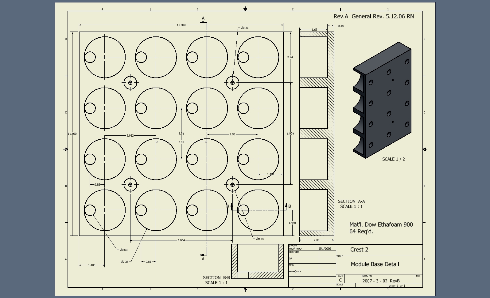
Crest Detector Module Shock Test
| Science Channel w/top Veto | 376 (actual) x 8 channels | 3008 |
| Side, inside & bottom veto w/supports | 370 | 370 |
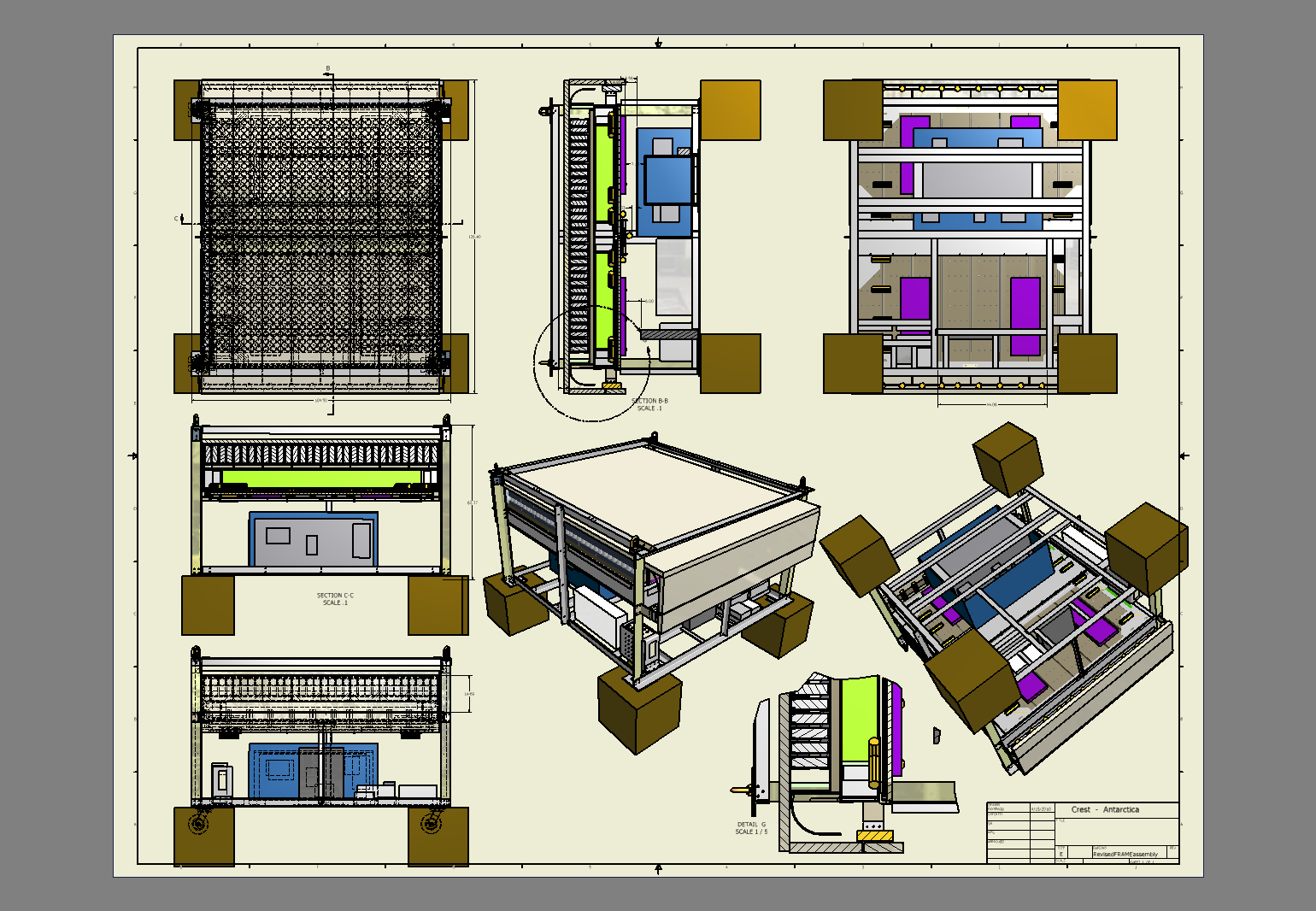
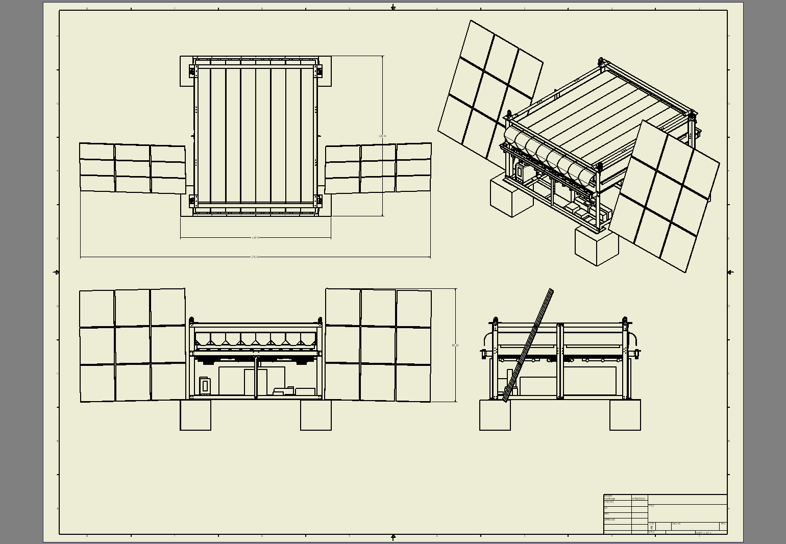
| Gondola structure | 795 | 795 |
| Electronics | 270 | 270 |
| Solar panels | 188 | 188 |
| Batteries & controller | 198 | 198 |
| Thermal control | 125 | 125 |
| Flight rigging | 110 | 110 |
| Total estimated Science/Gondola Instrument | 5064 lbs (2297 kg) | |
| CSBF -above pin | 647 | 647 |
| CSBF -below pin | 675 | 675 |
| Antenna boom | 12 | 12 |
| Rotator | 177 | 177 |
| Ballast | 500 (TBD) | 500 |
| Crush pad | 0 (TBD) | 0 |
| Total estimated weight | 7075 lbs. (3209 kg) |
Download spreadsheet of above table
1 |
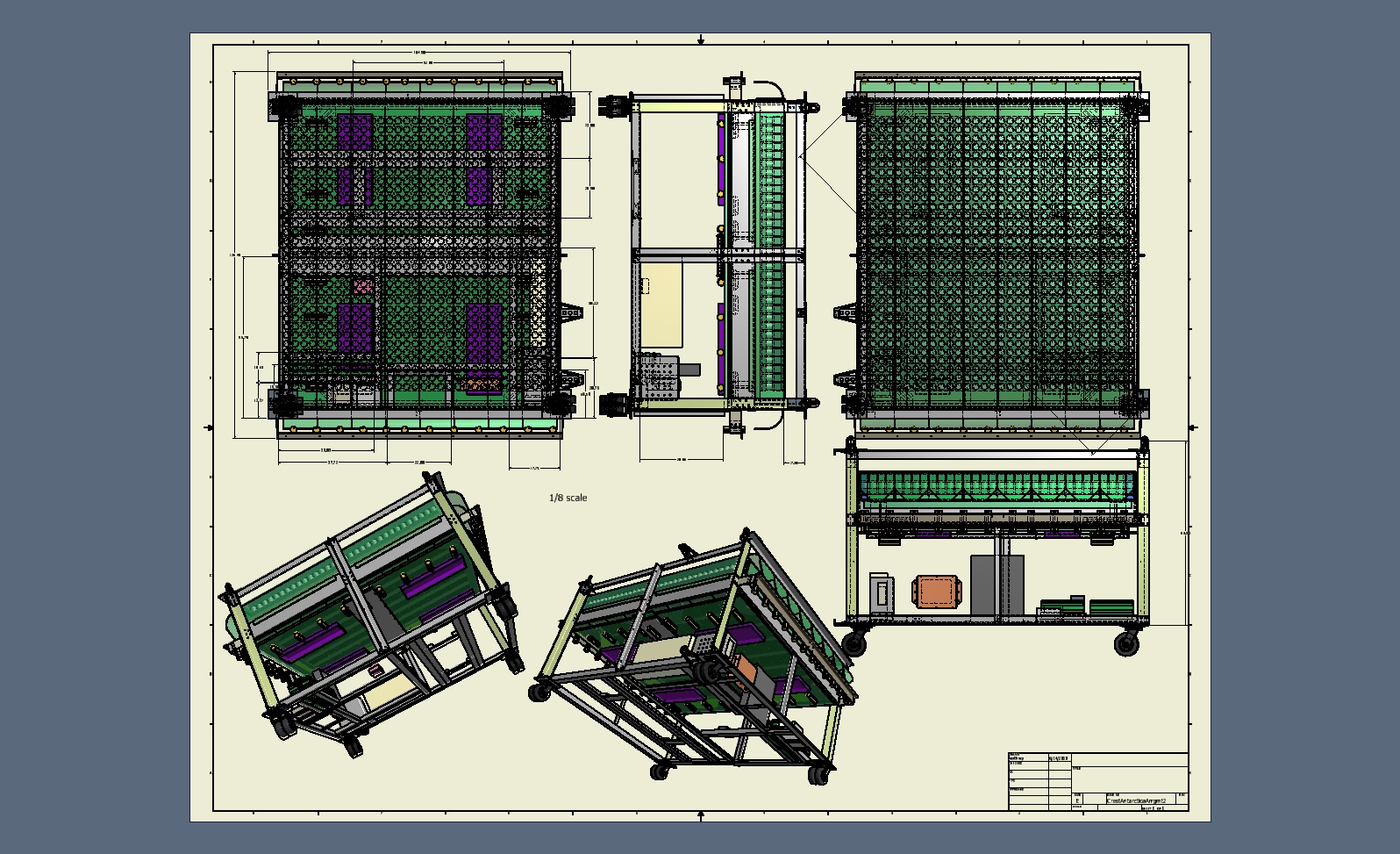
 2 Bottom surface of bottom veto with electronics |
 3 |
 4 |
 5 |
 6 |
 7 |
 8 |
 9 |
 10 |
 11 |
 12 |
 13 |
 14 |
 15 |
 16 |
 17 |
 18 Science channel with top foam and top veto paddle removed |
 19 |
 20 |
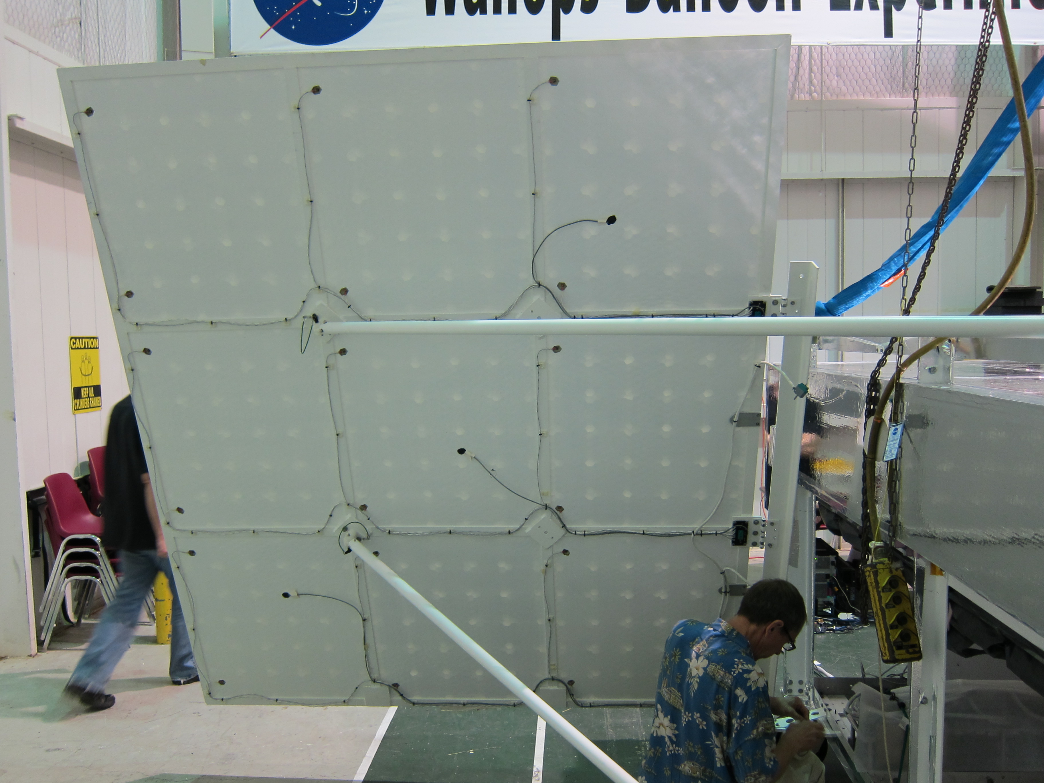
 21 Science channel deflection during upside-down hang before center clips added |
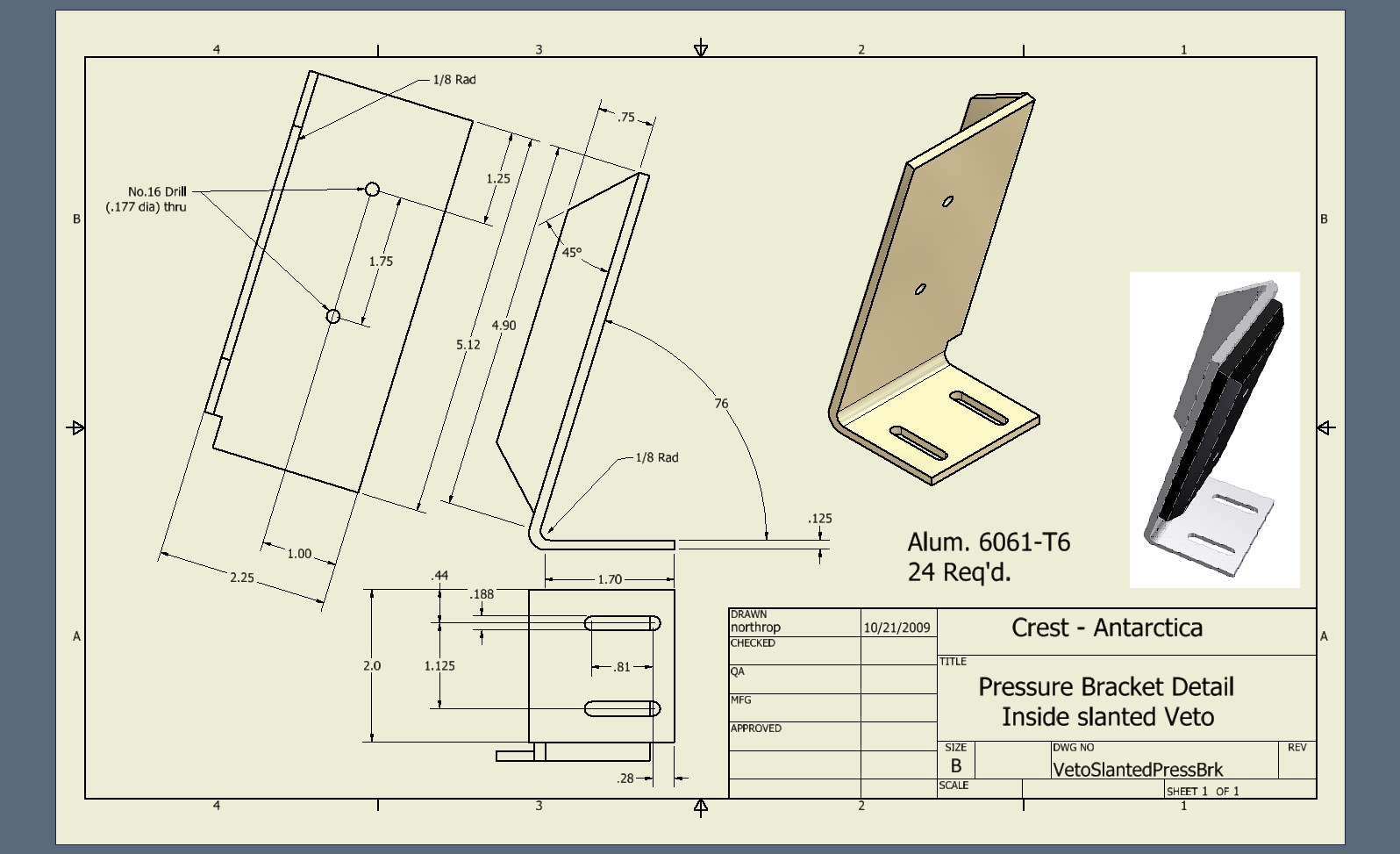
 22 |
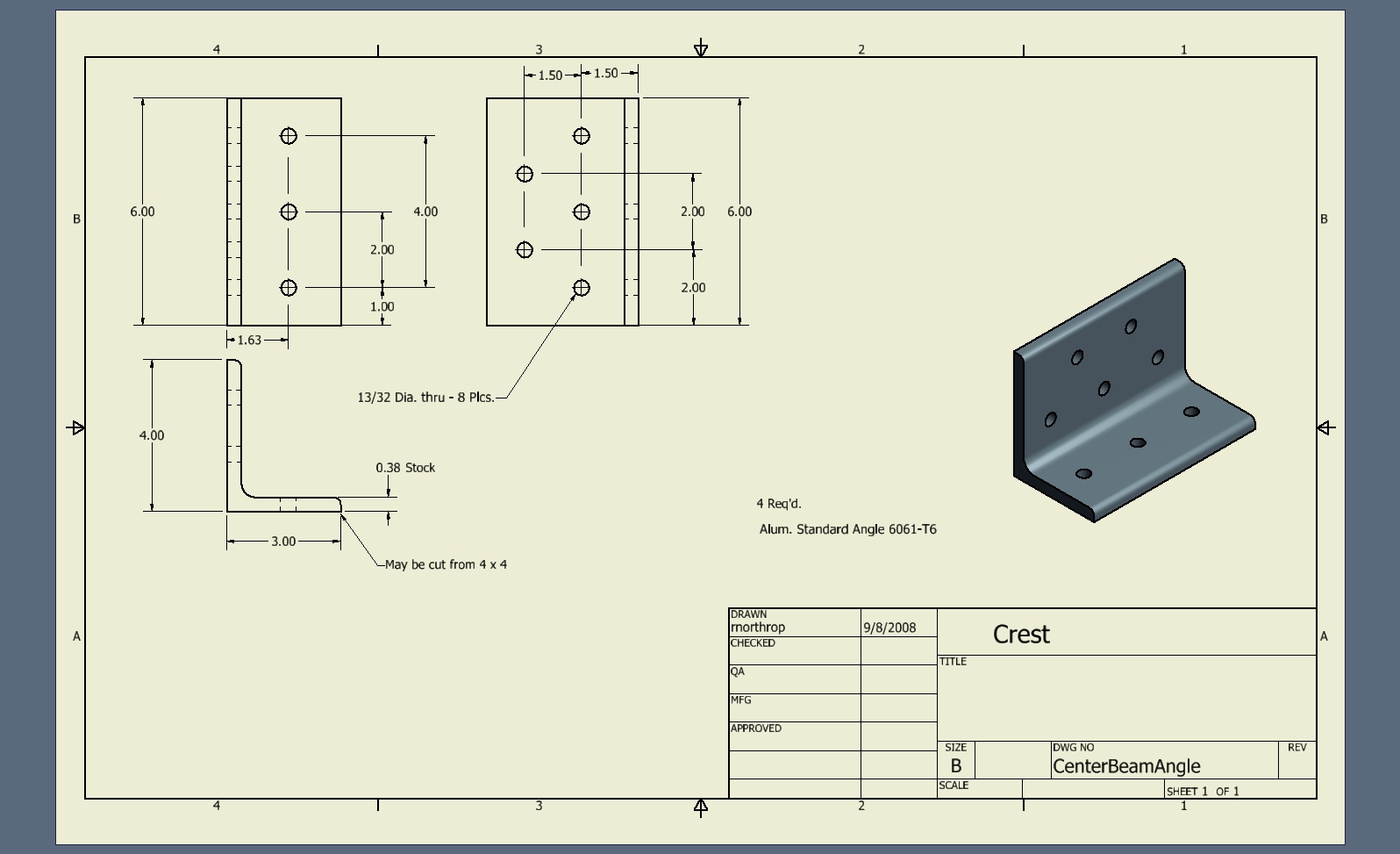
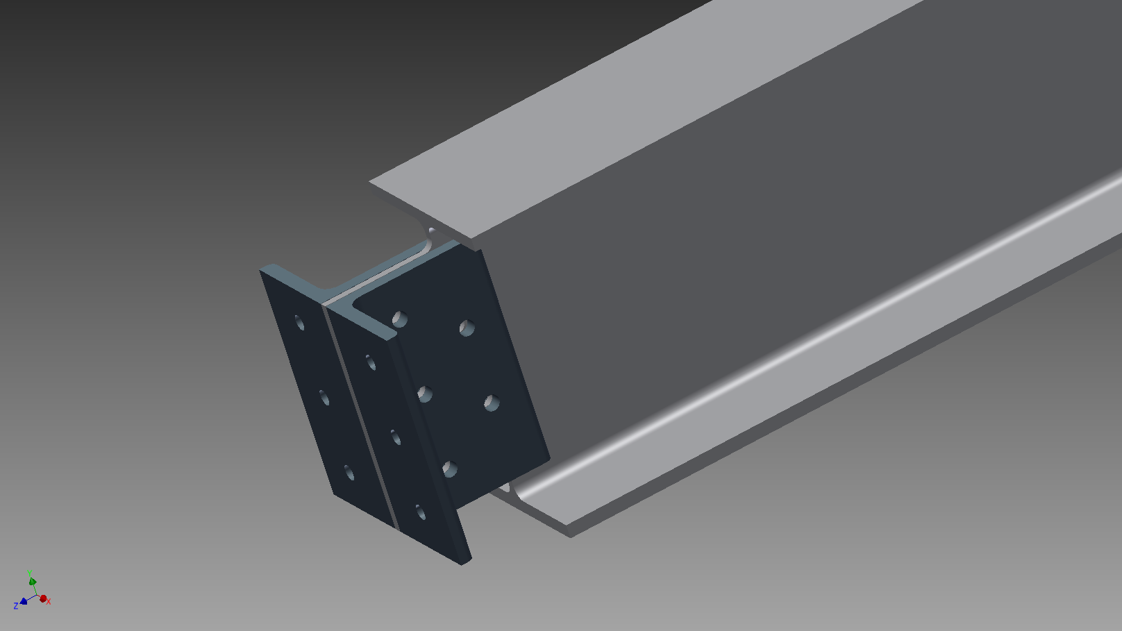
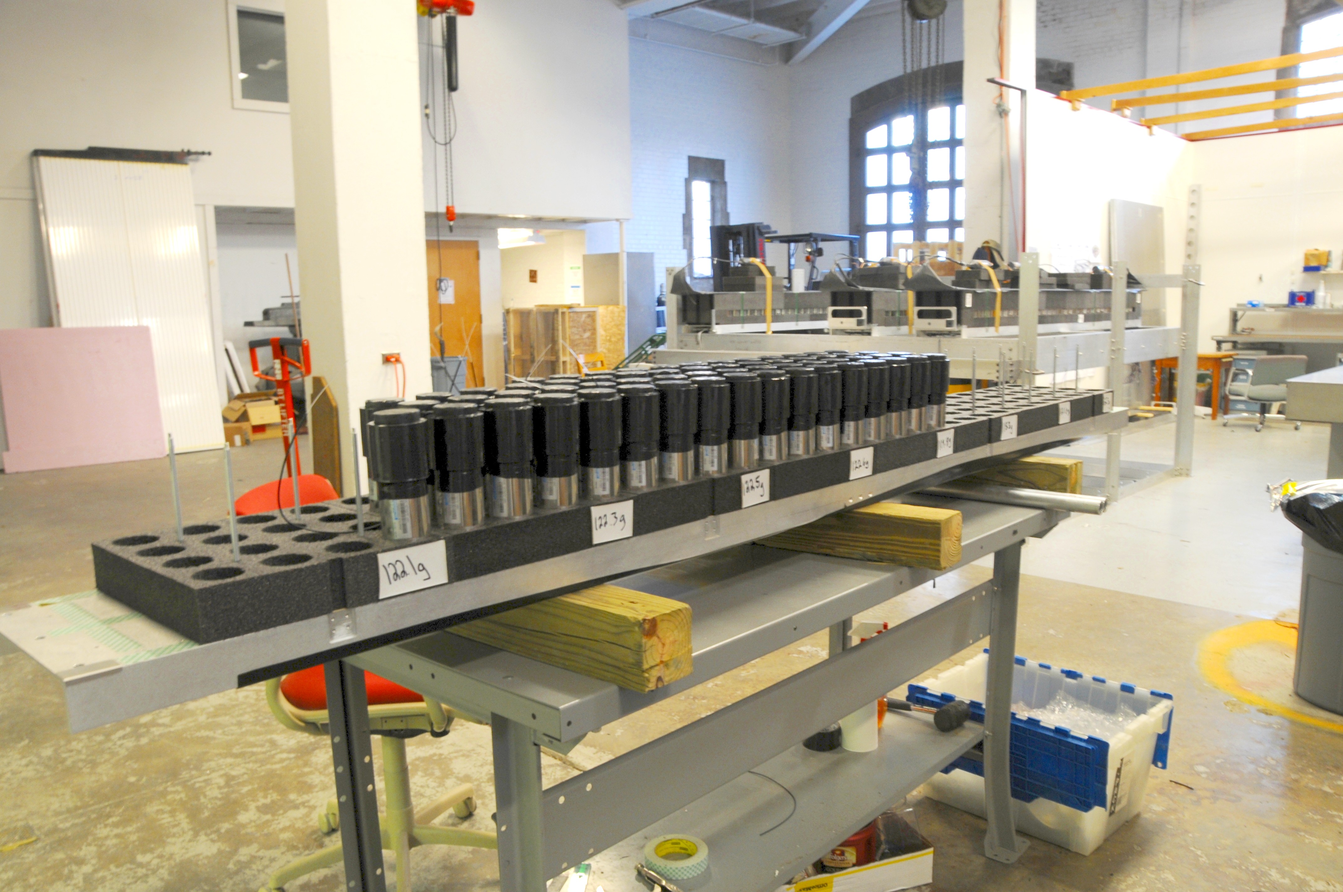
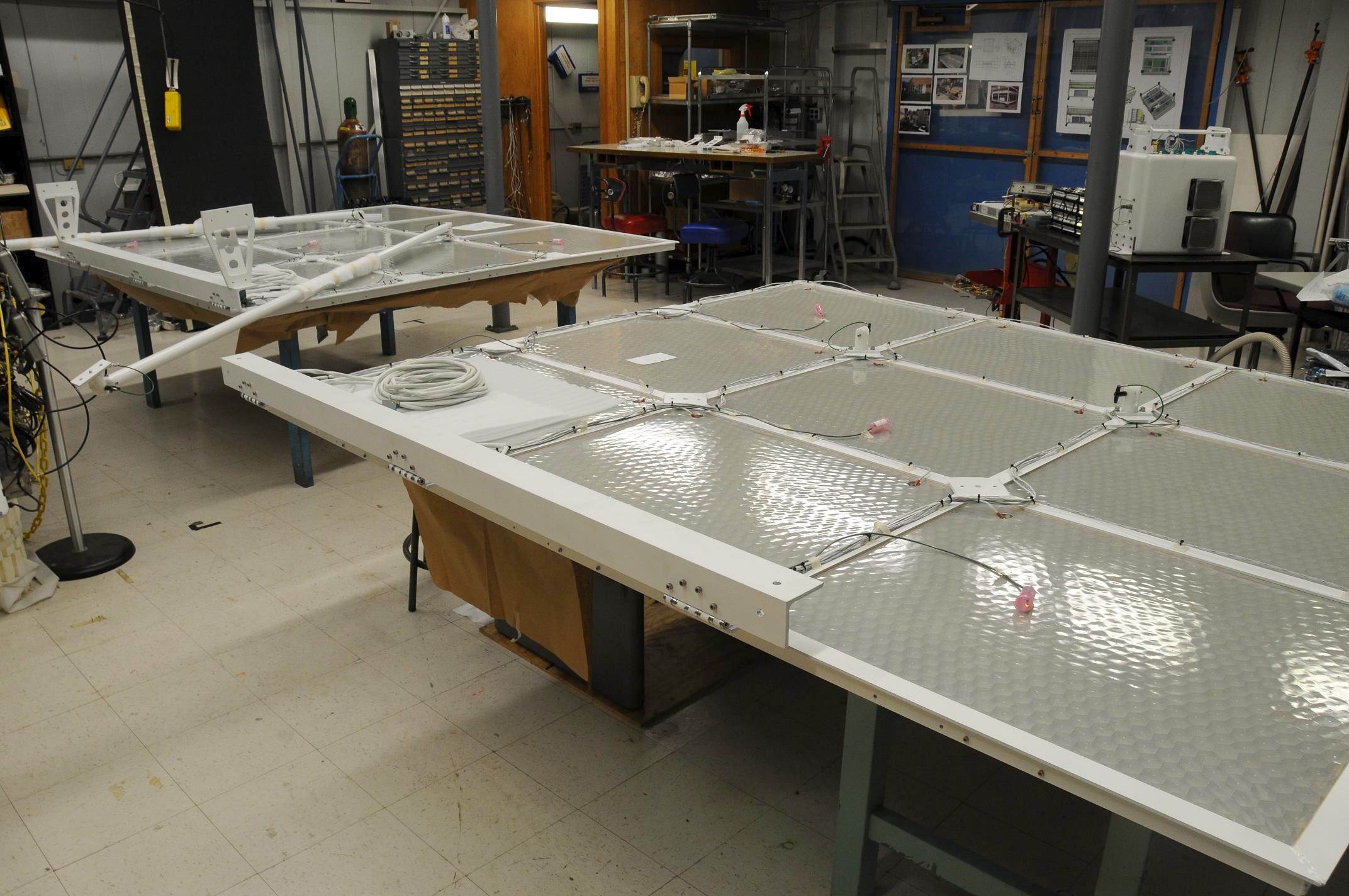
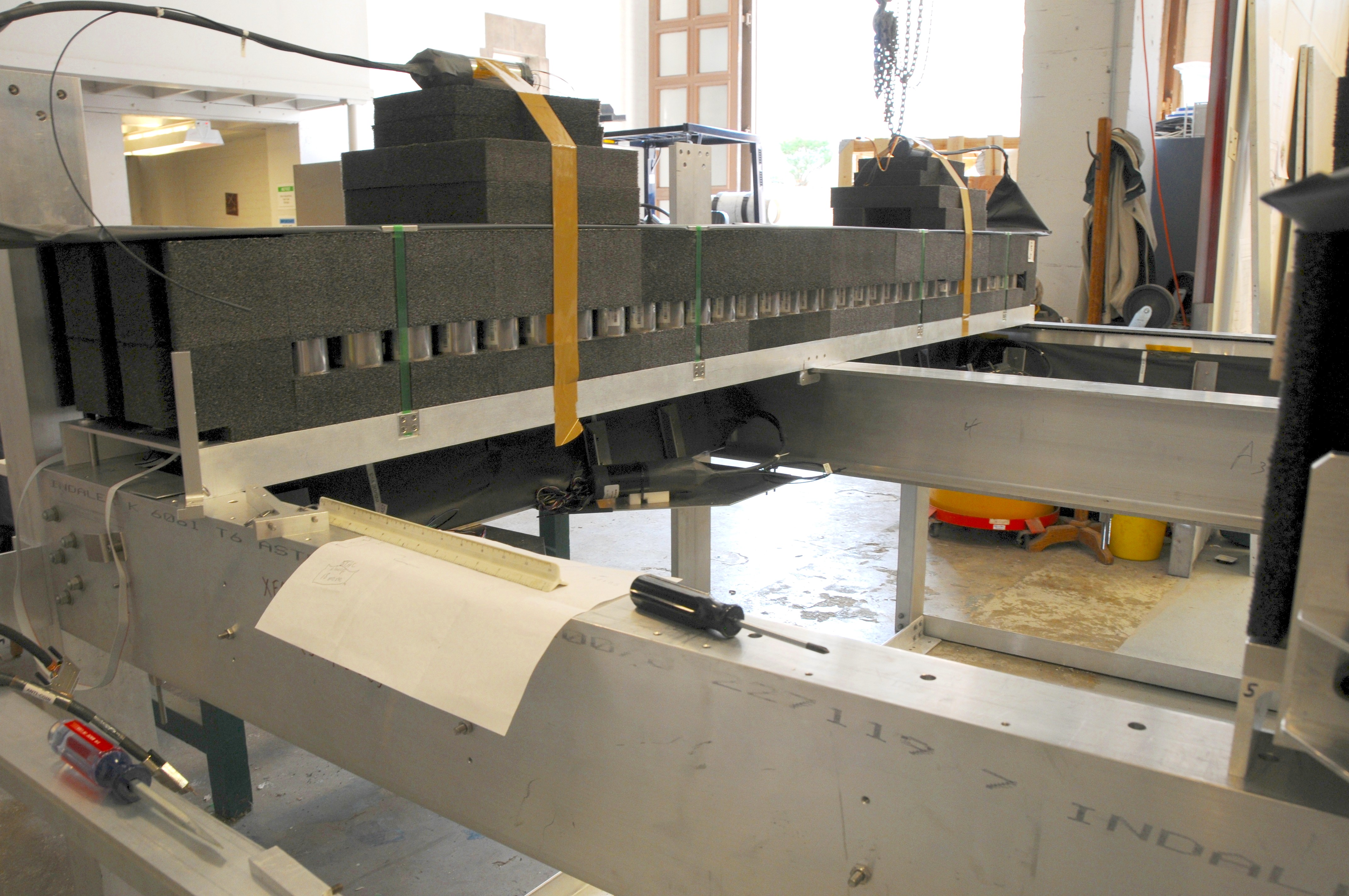 23 Fully assembled science channel |
 24 |
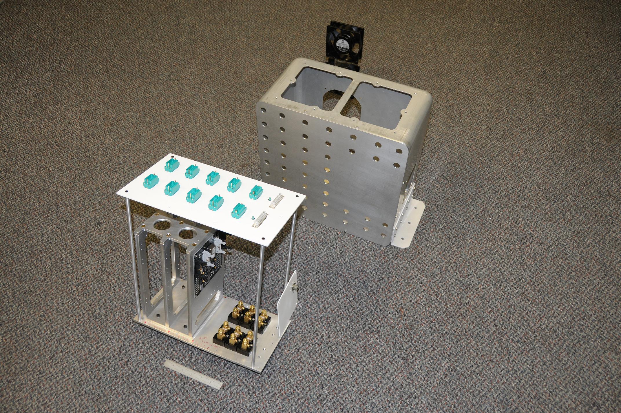
 25 Crest ConnUS test instrument |
 26 |
 27 |
 28 |
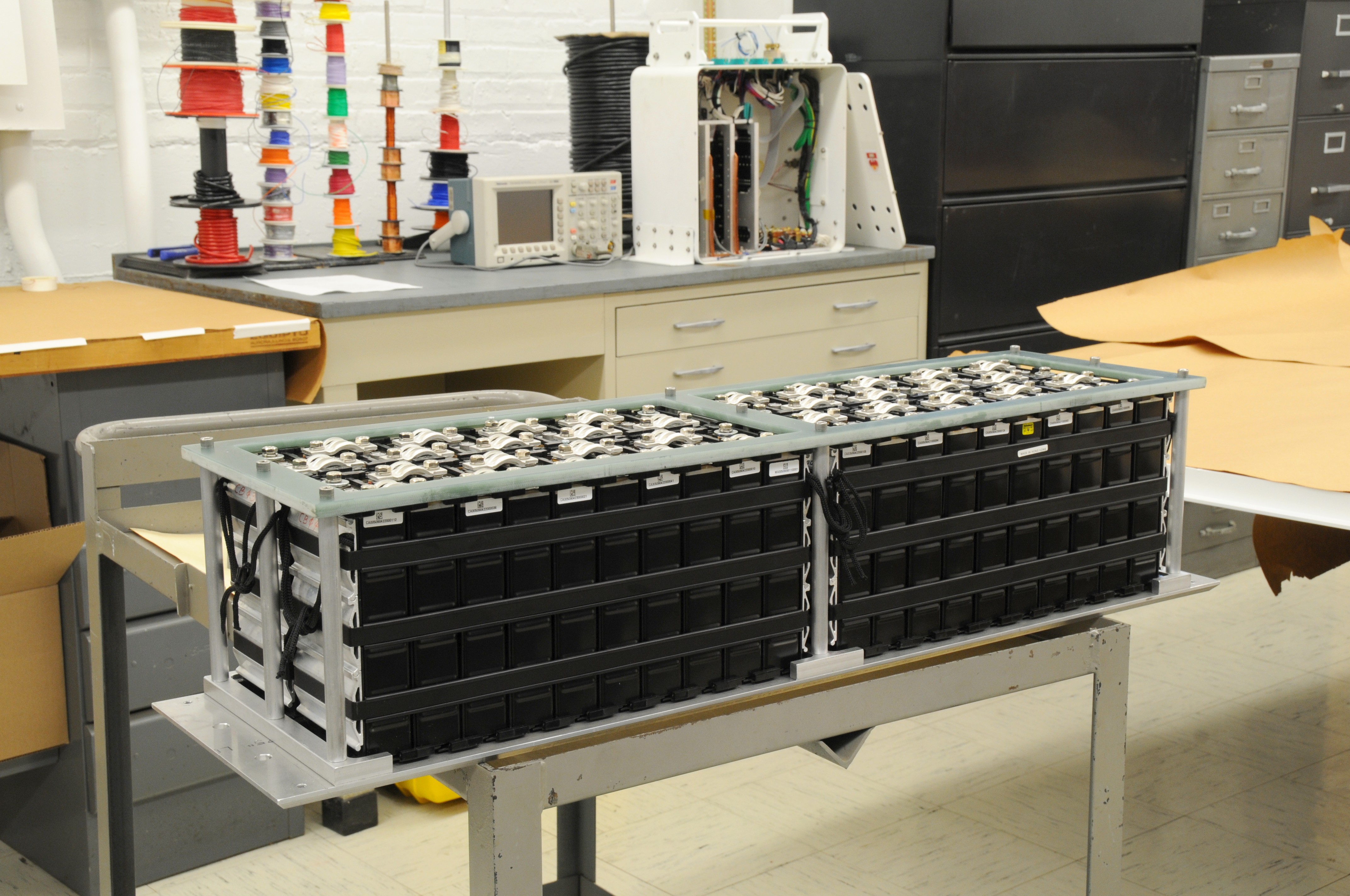
 29 |
 30 |
 31 |
 32 |
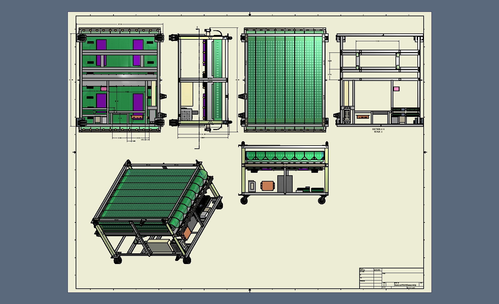
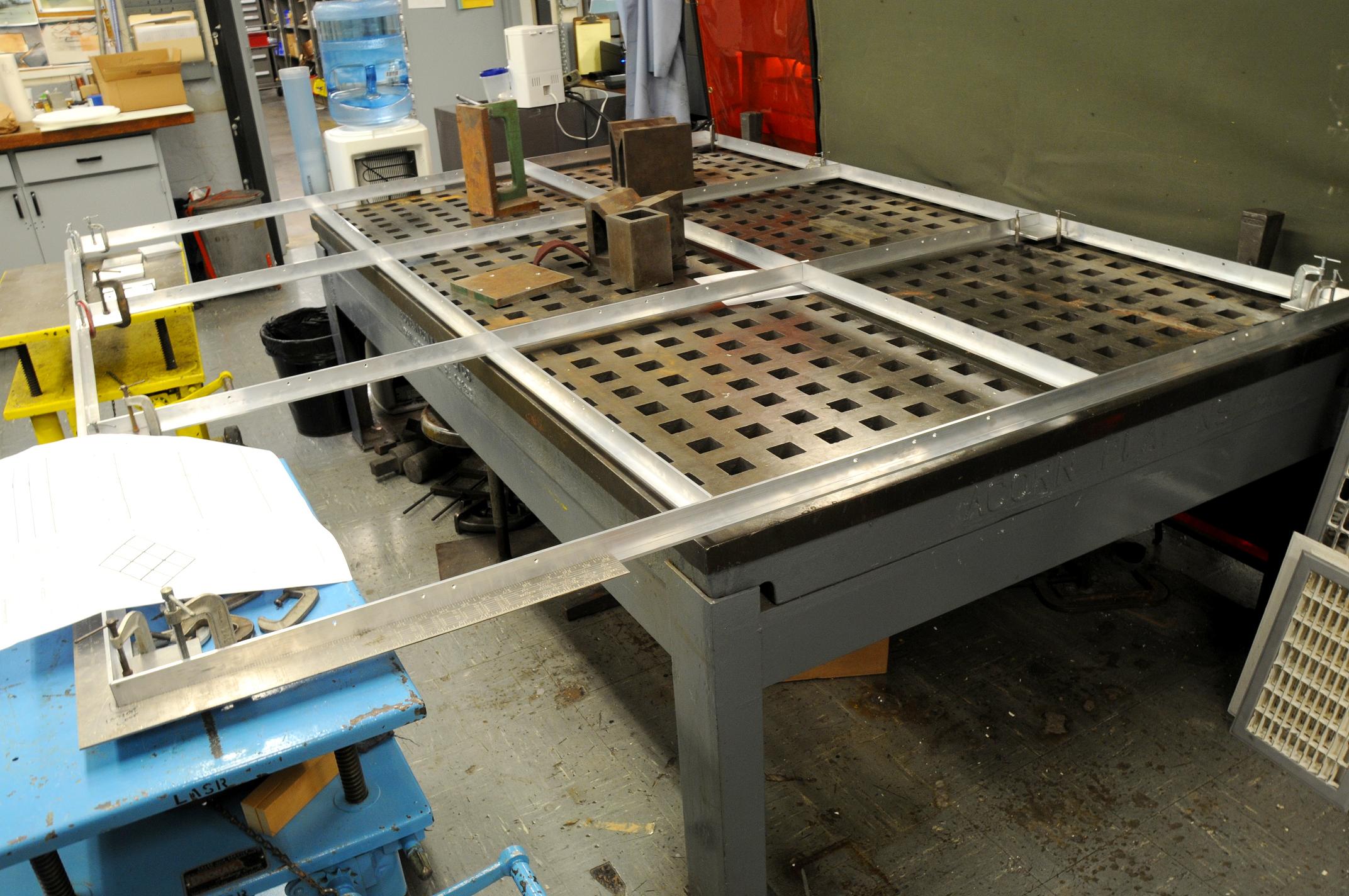
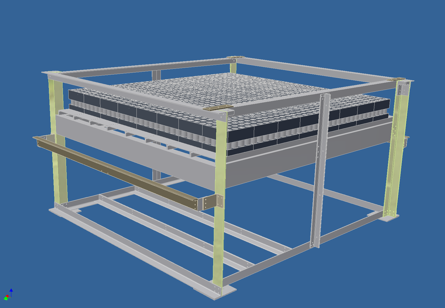
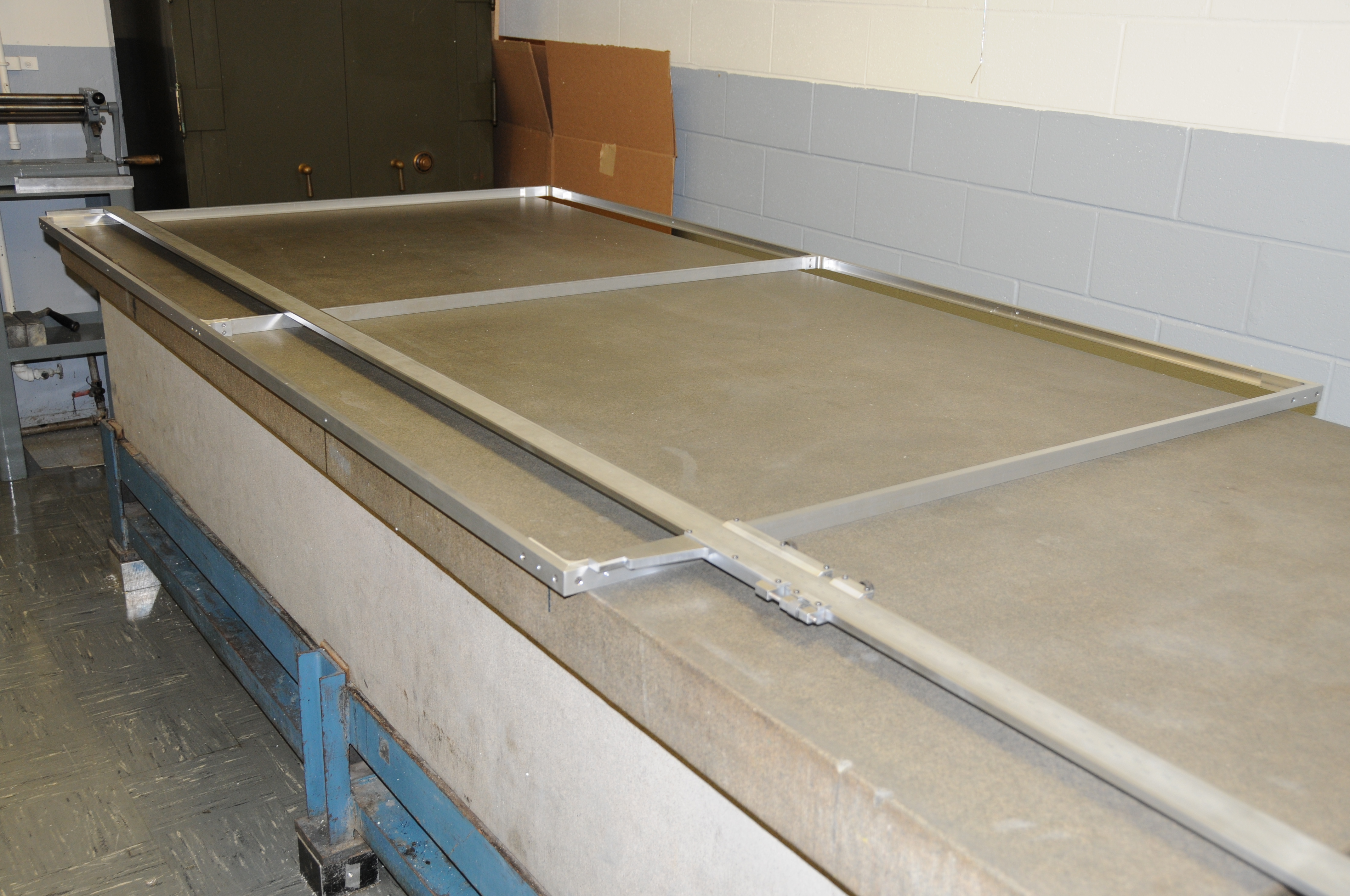
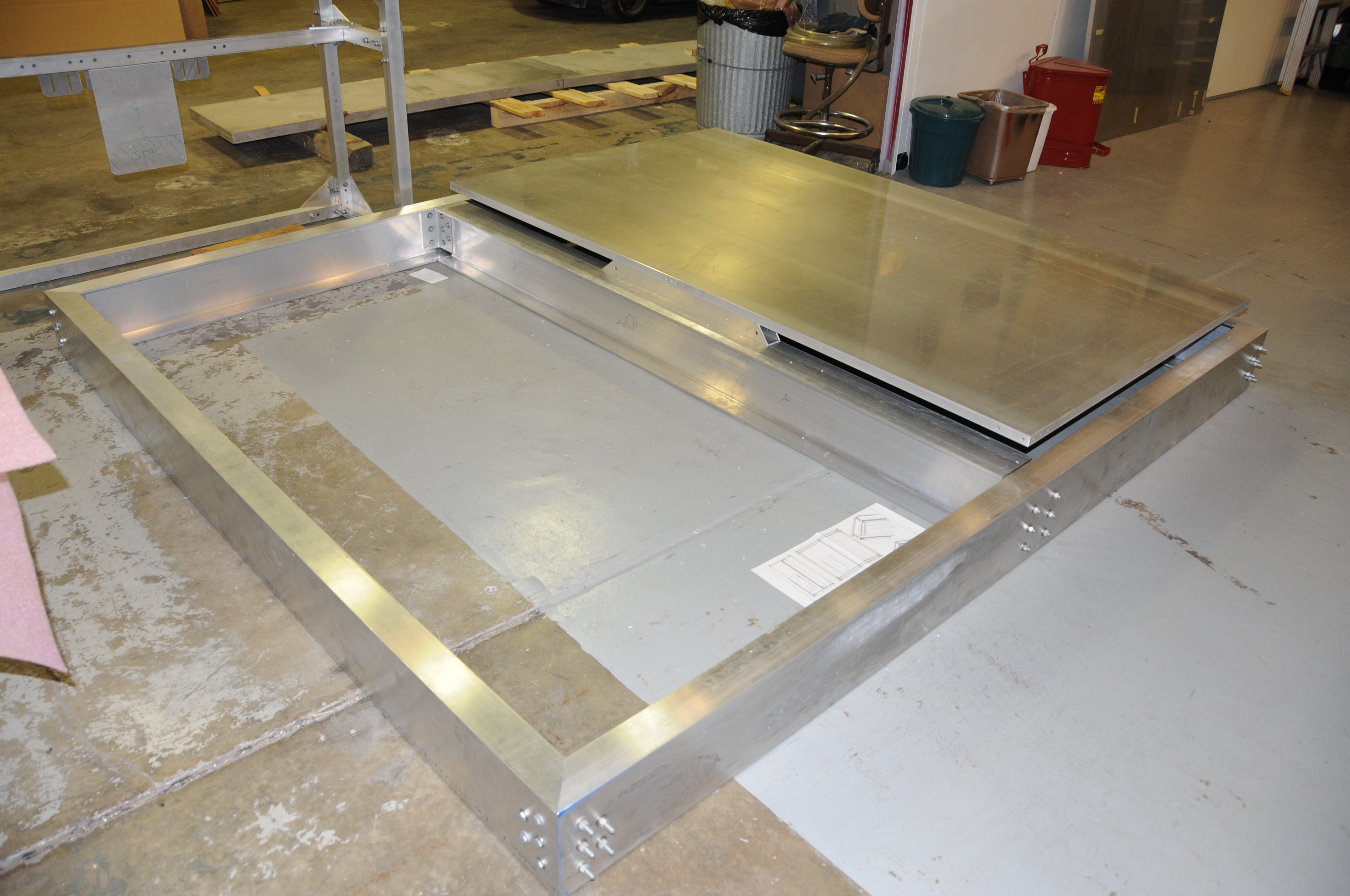 33 Platform with honeycomb during fit-check |
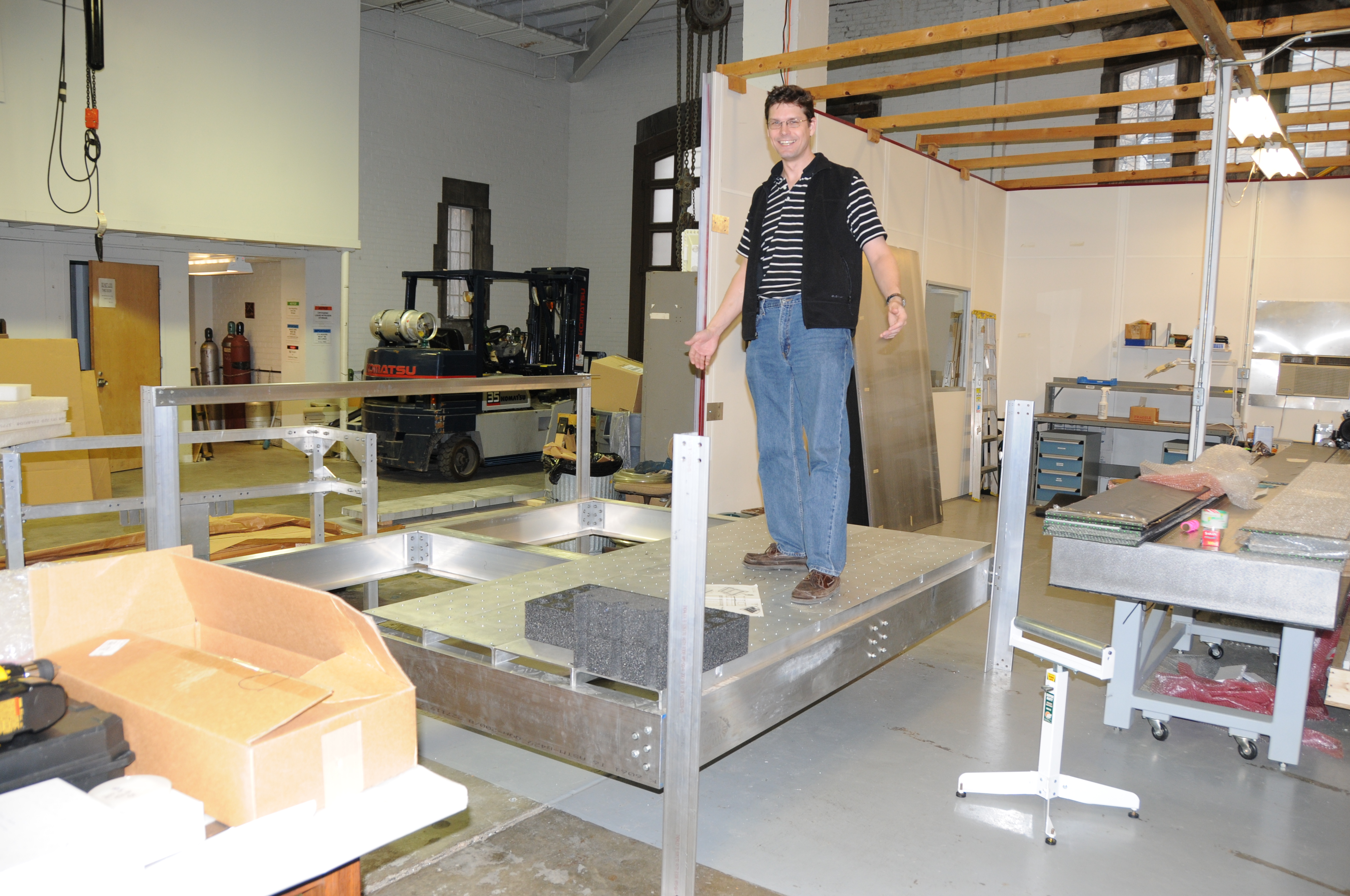 34 Scott Wakely jumping on science channels |
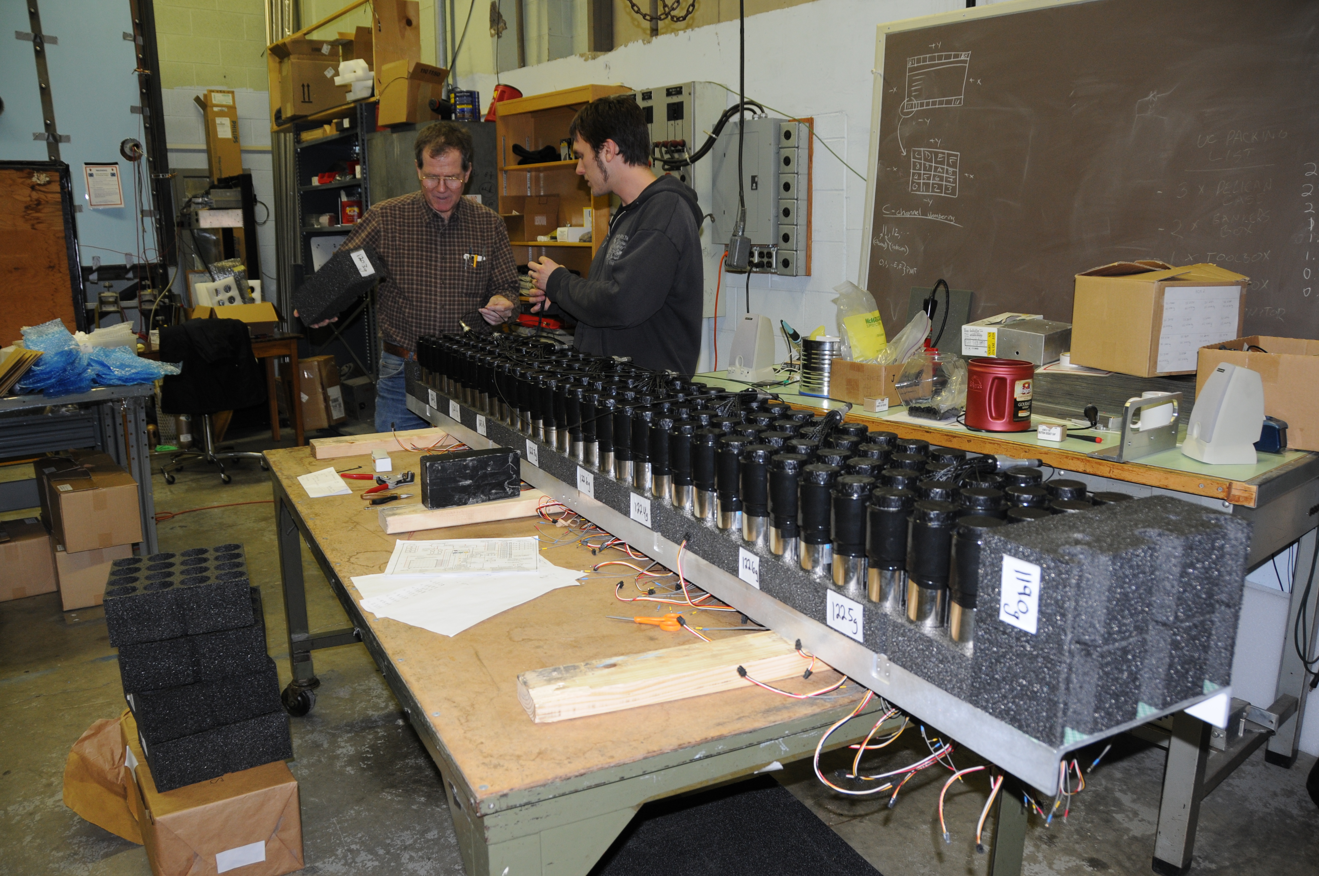 35 Chuck Bower and Alex Shoyer assembling science channel |
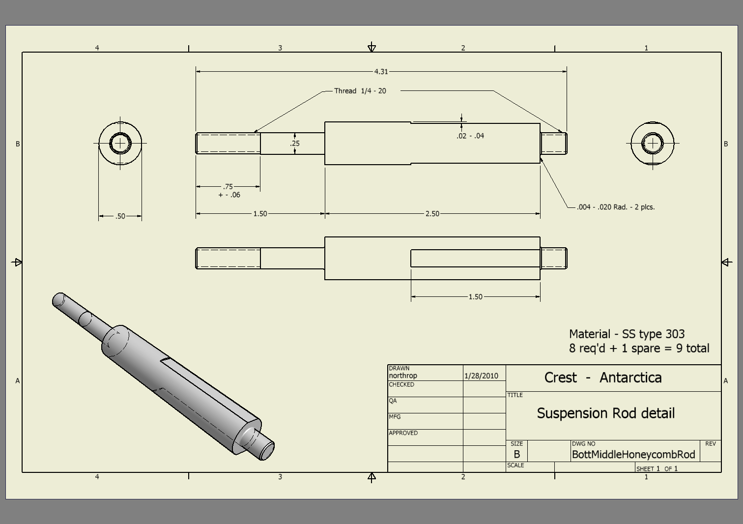
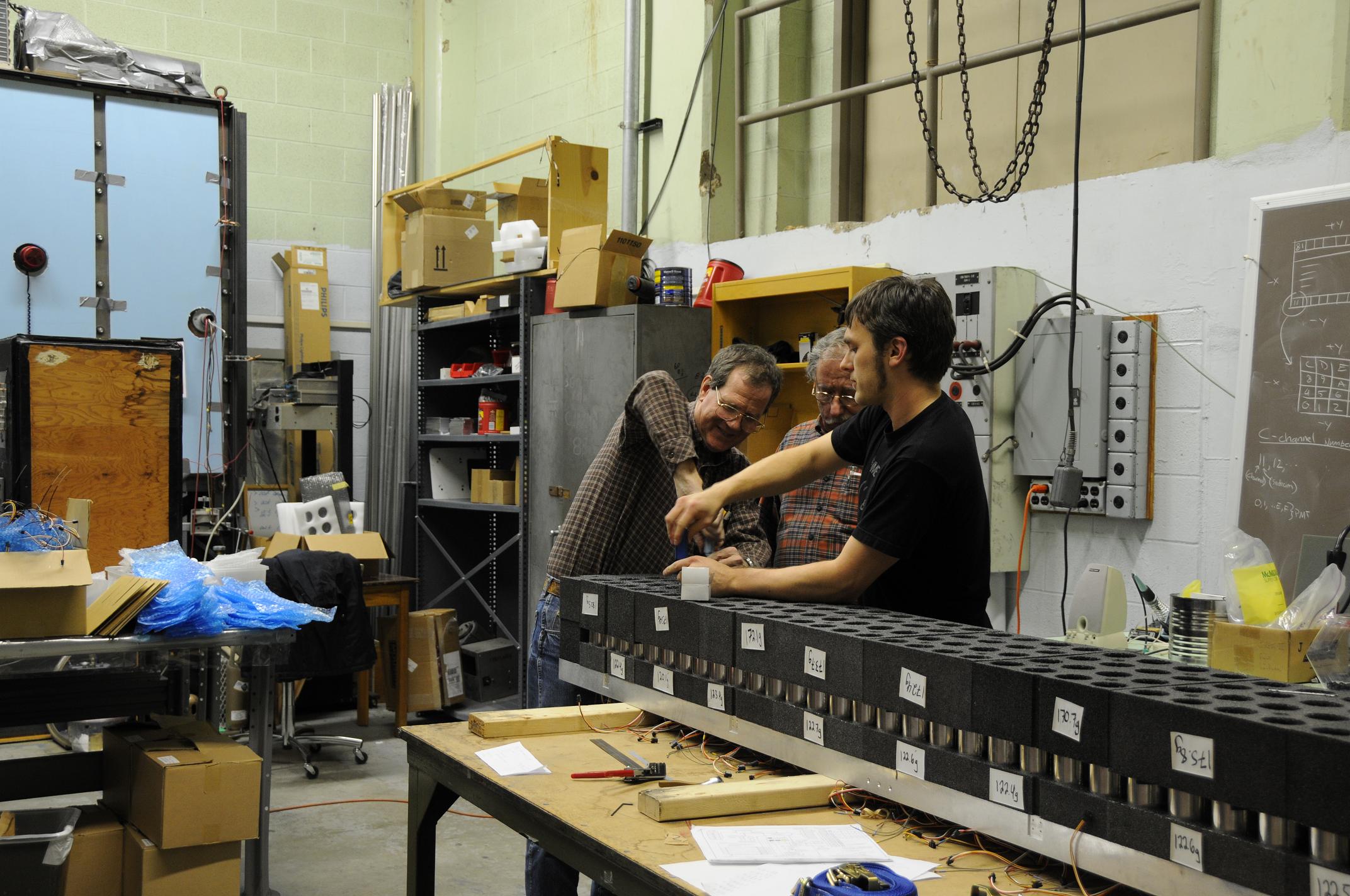 36 Chuck Bower and Alex Shoyer installing module hold-down rods |
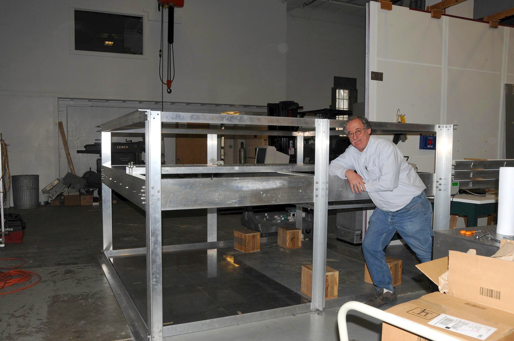 37 Rich Northrop during early gondola assembly |
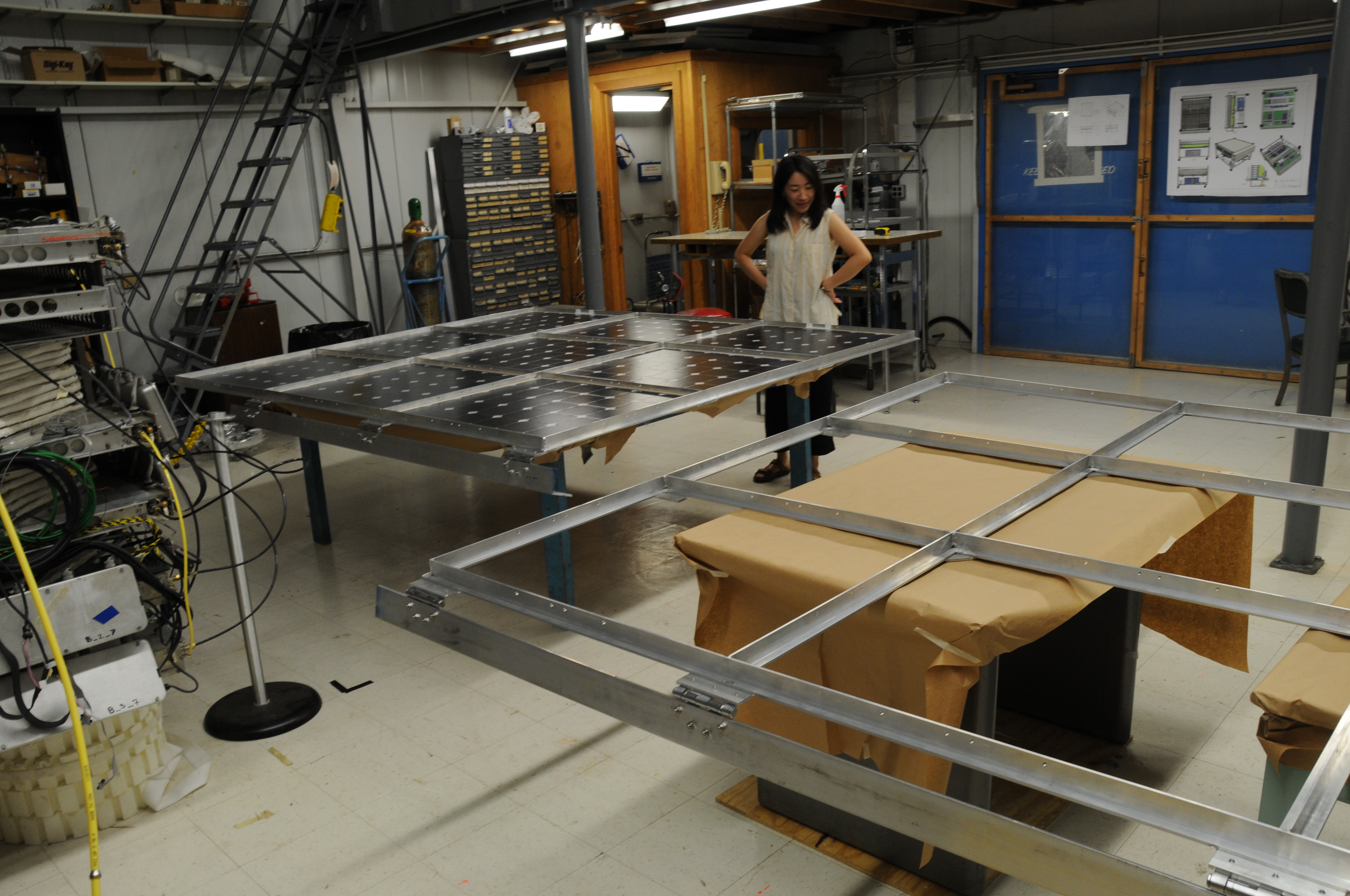
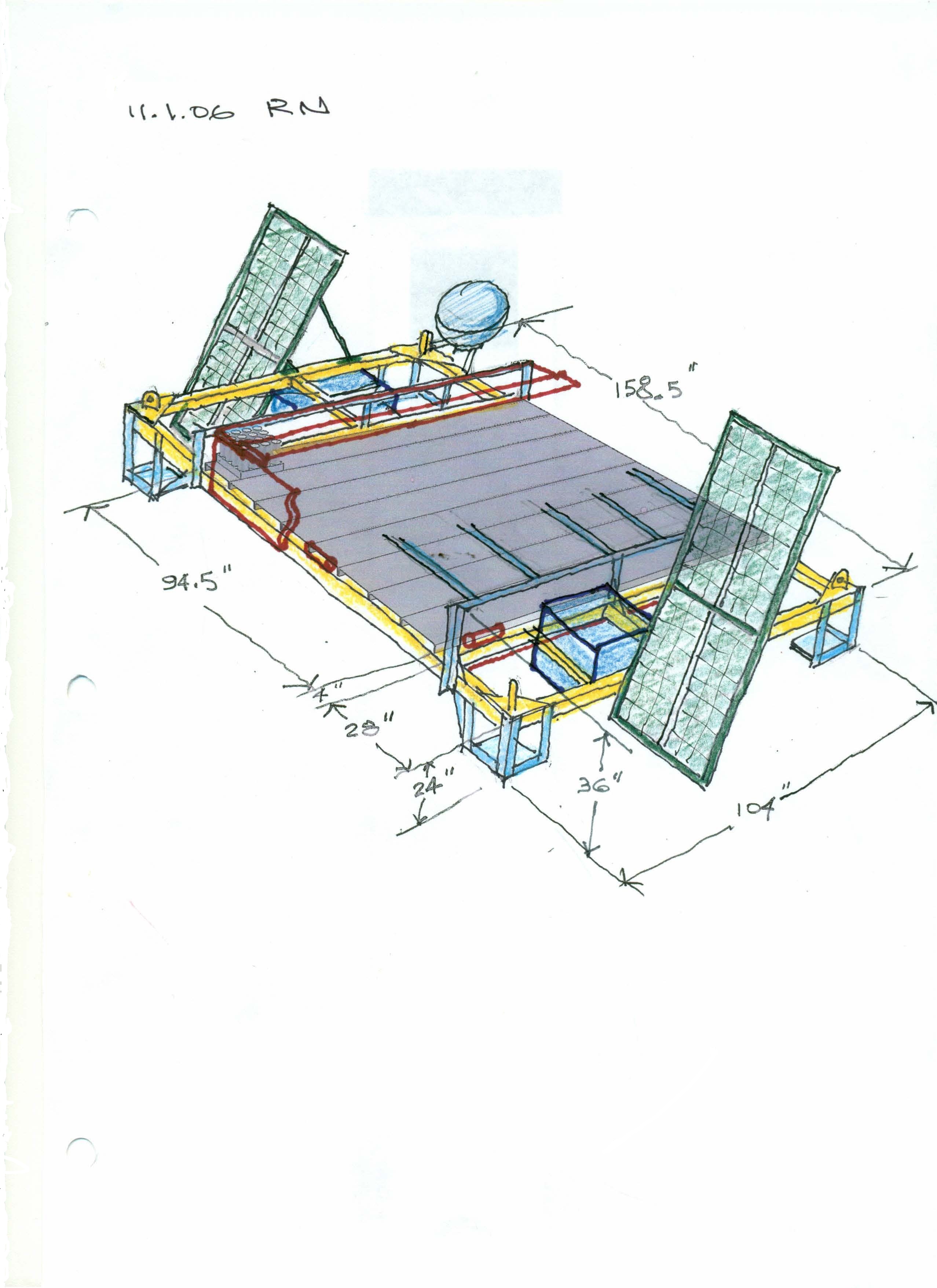
 38 Balsa model showing solar panel rotation with Nahee Park holding science channel |
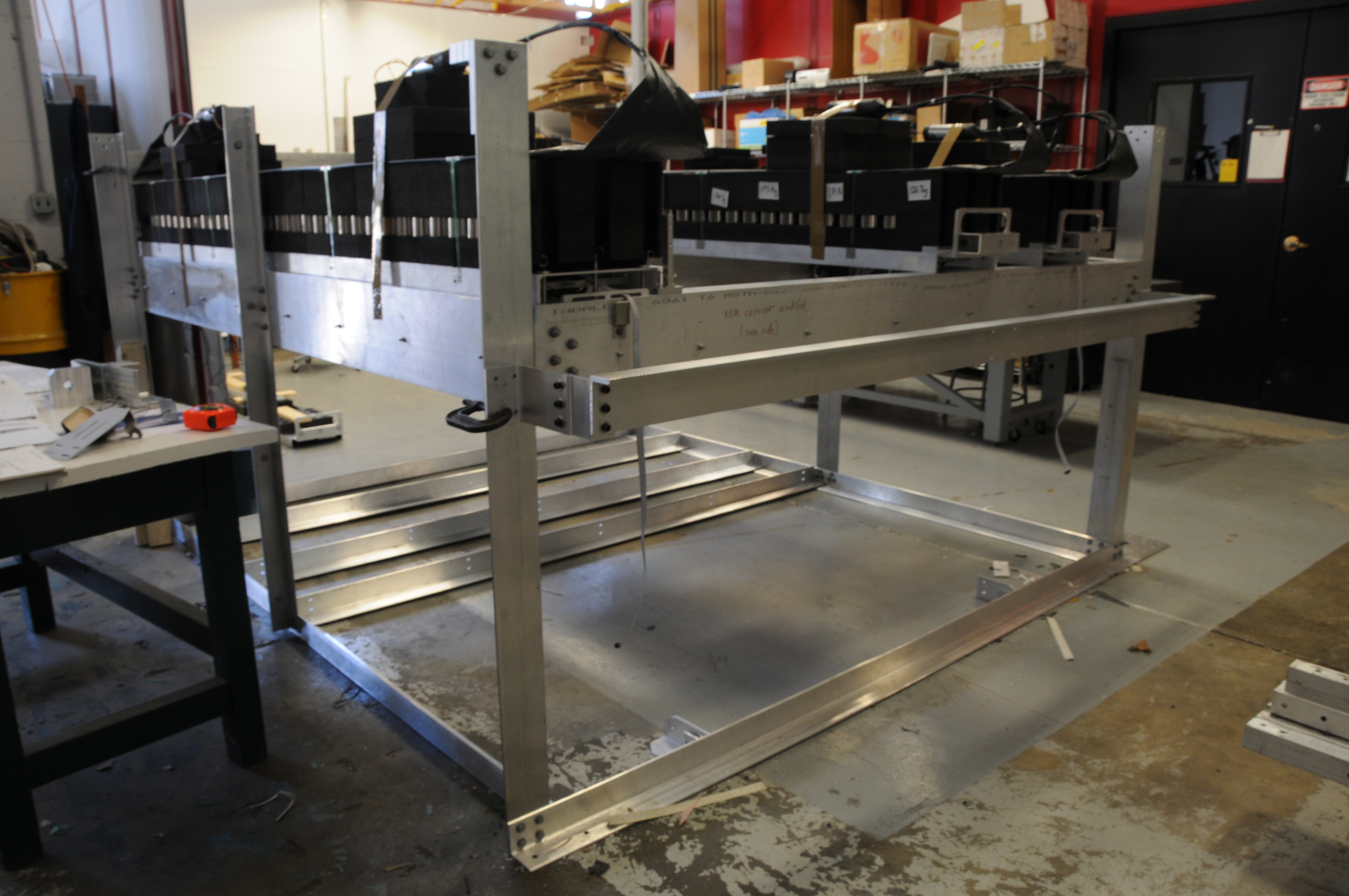 39 First three science channels assembled on platform with end handling brackets showing |
 40 Indiana University assembly lab |
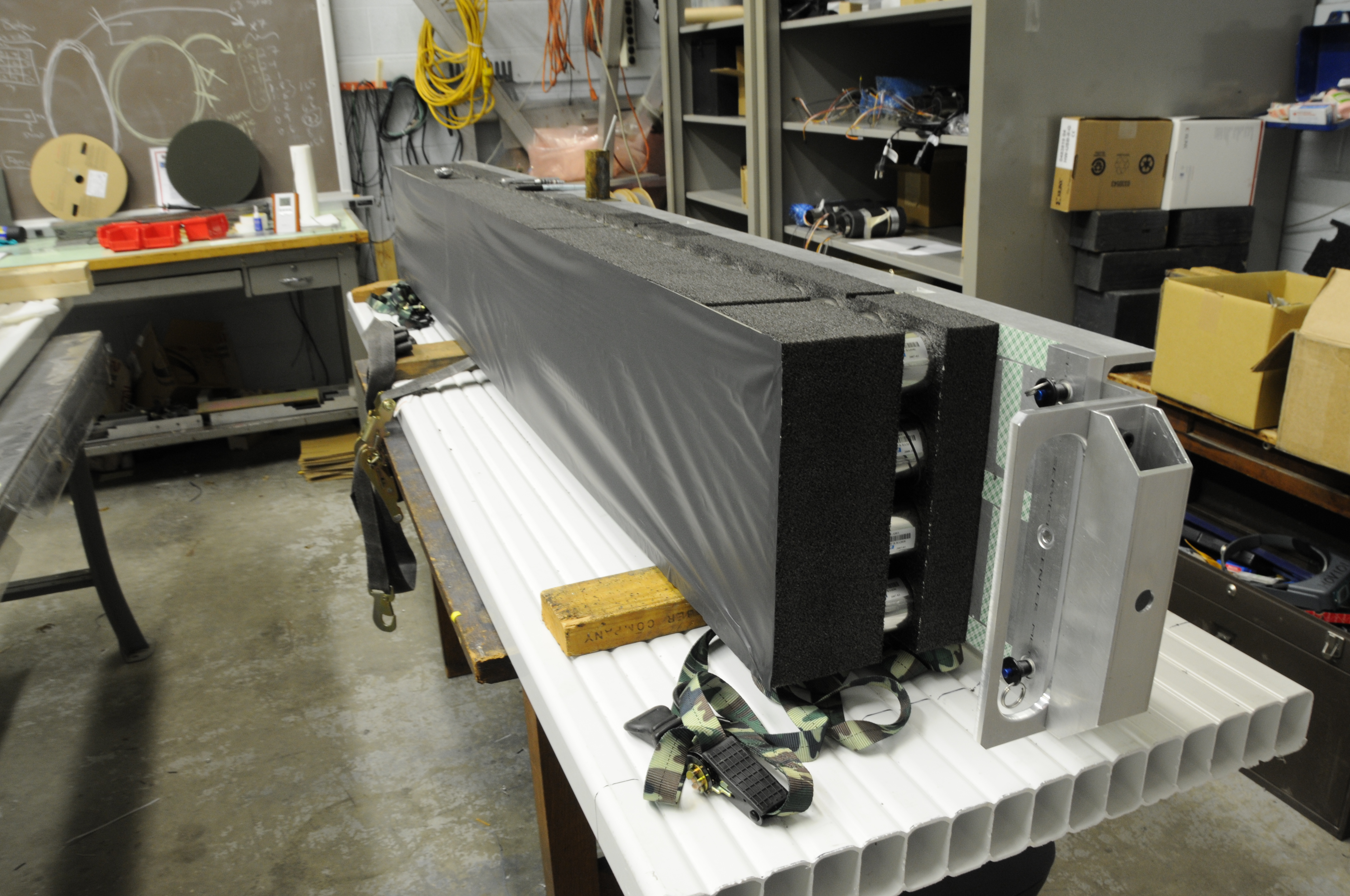 41 Science channel with top light seal |
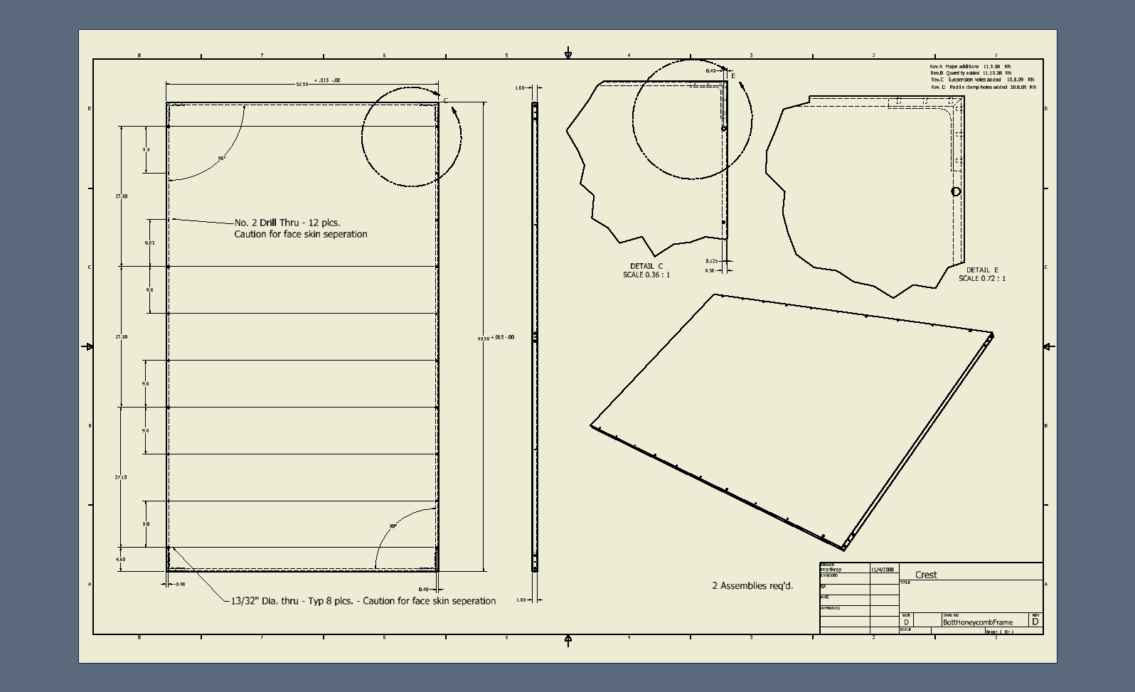
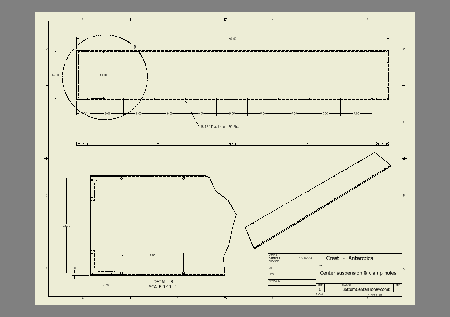
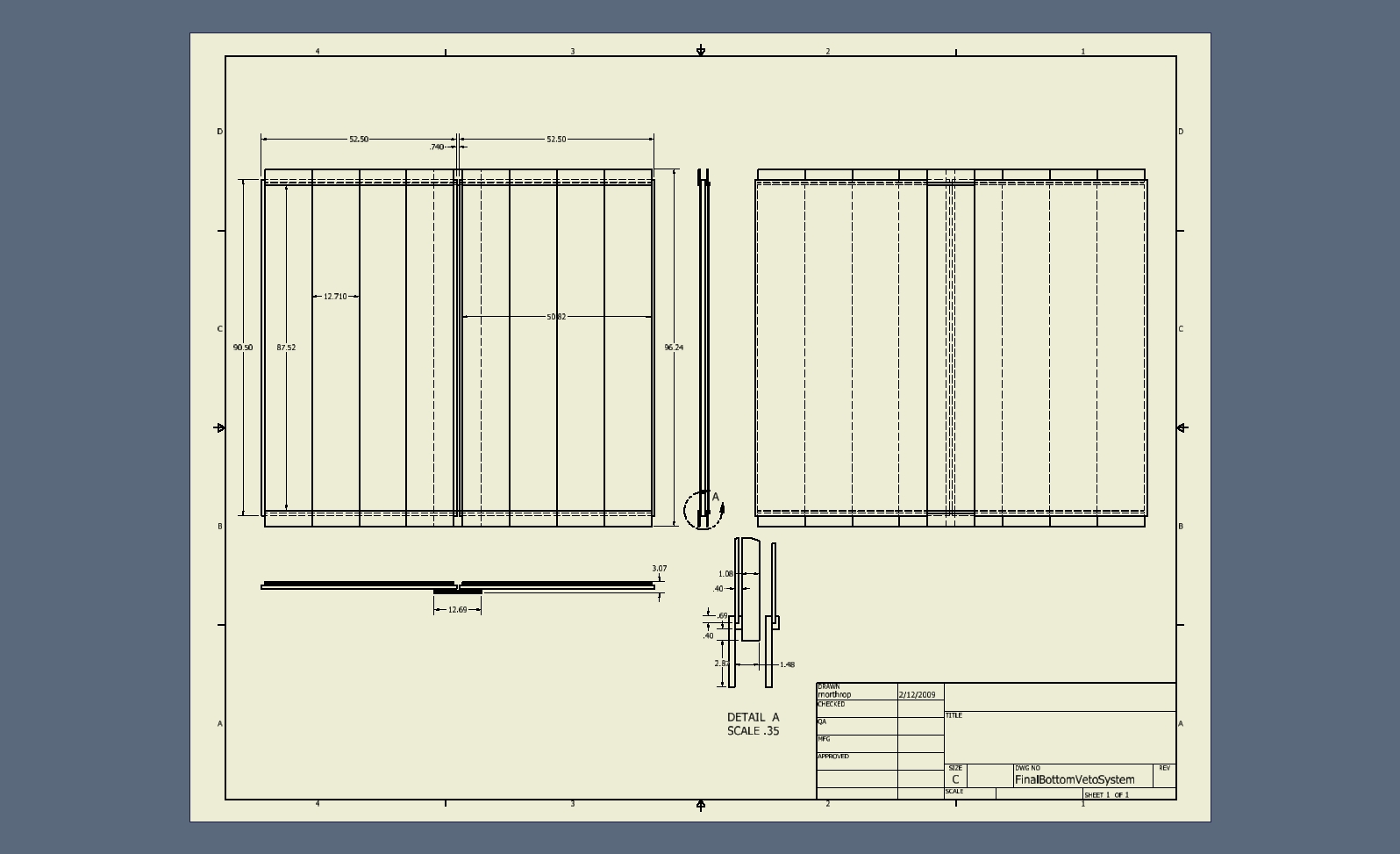
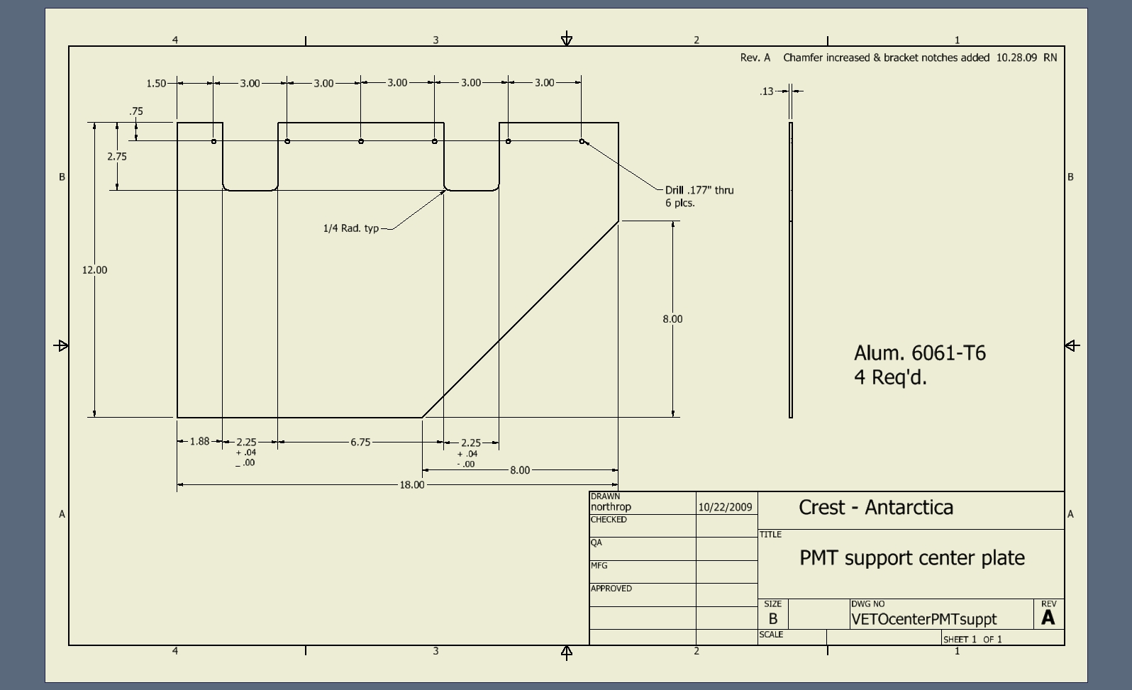
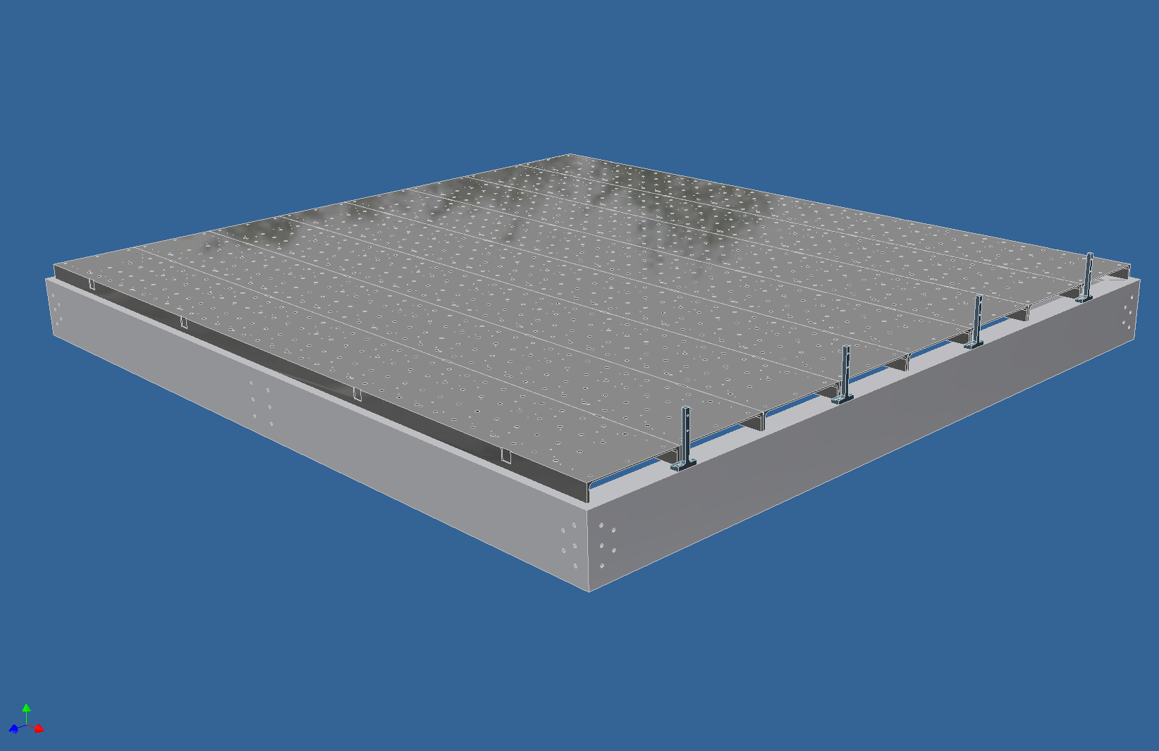
 42 Center bottom veto support honeycomb panel |
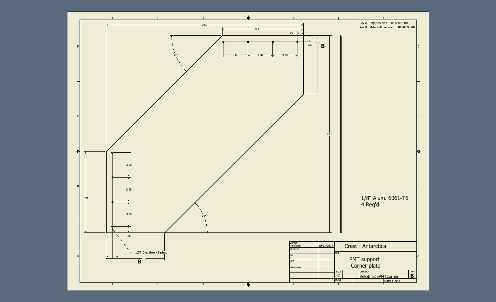
 43 Corner slanted inside veto PMTs |
 44 Science channel center hold-down clip and slanted center veto PMTs |
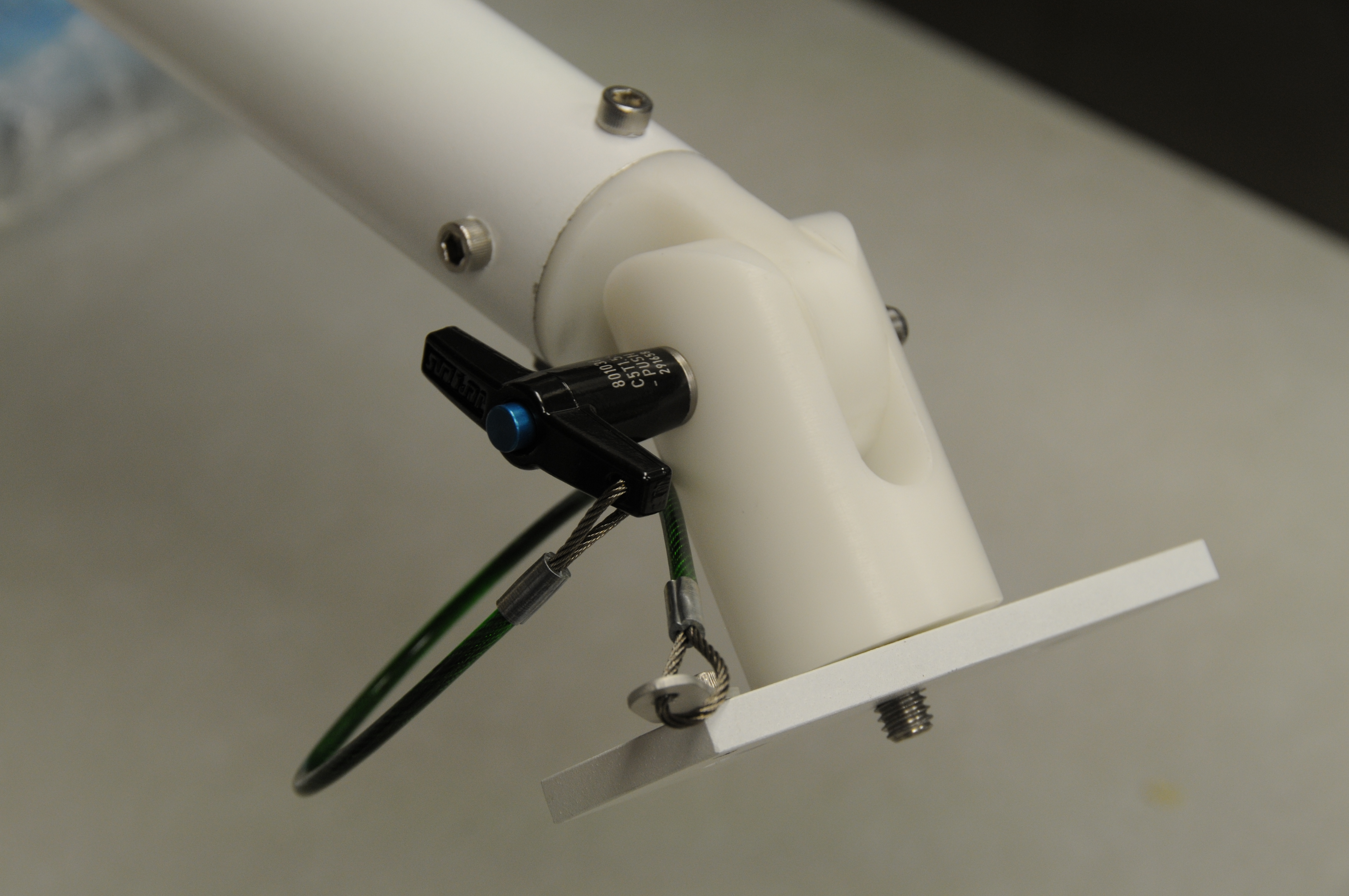
 45 Side veto clamp review |
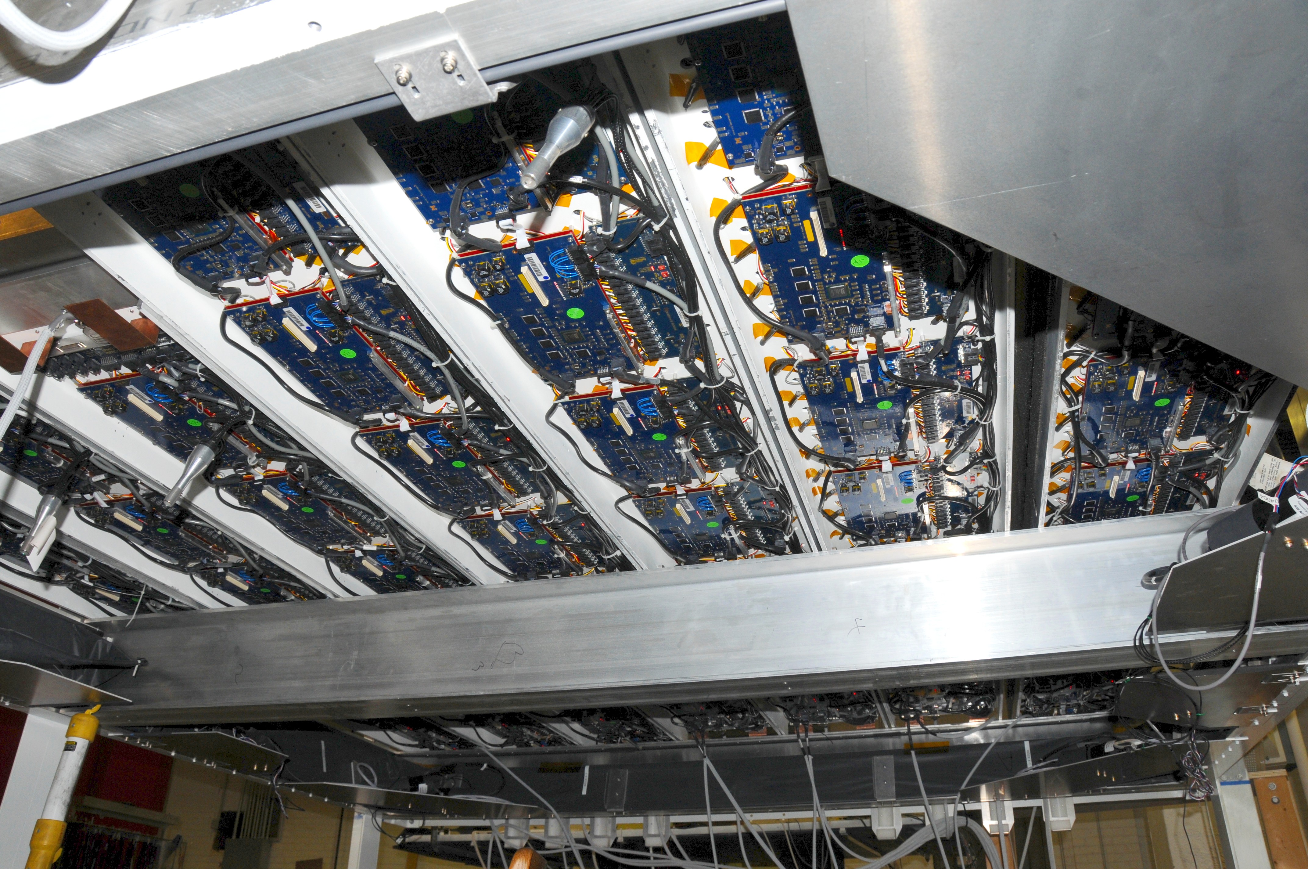 46 Bottom view showing channel electronics |
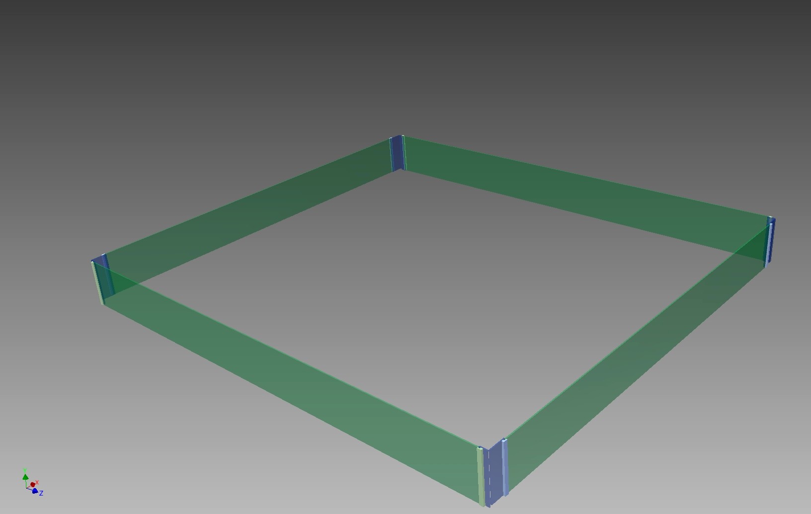
 47 Solar panel frame being welded |
 48 Nahee Park checking first solar panel assembly |
 49 Batteries during assembly |
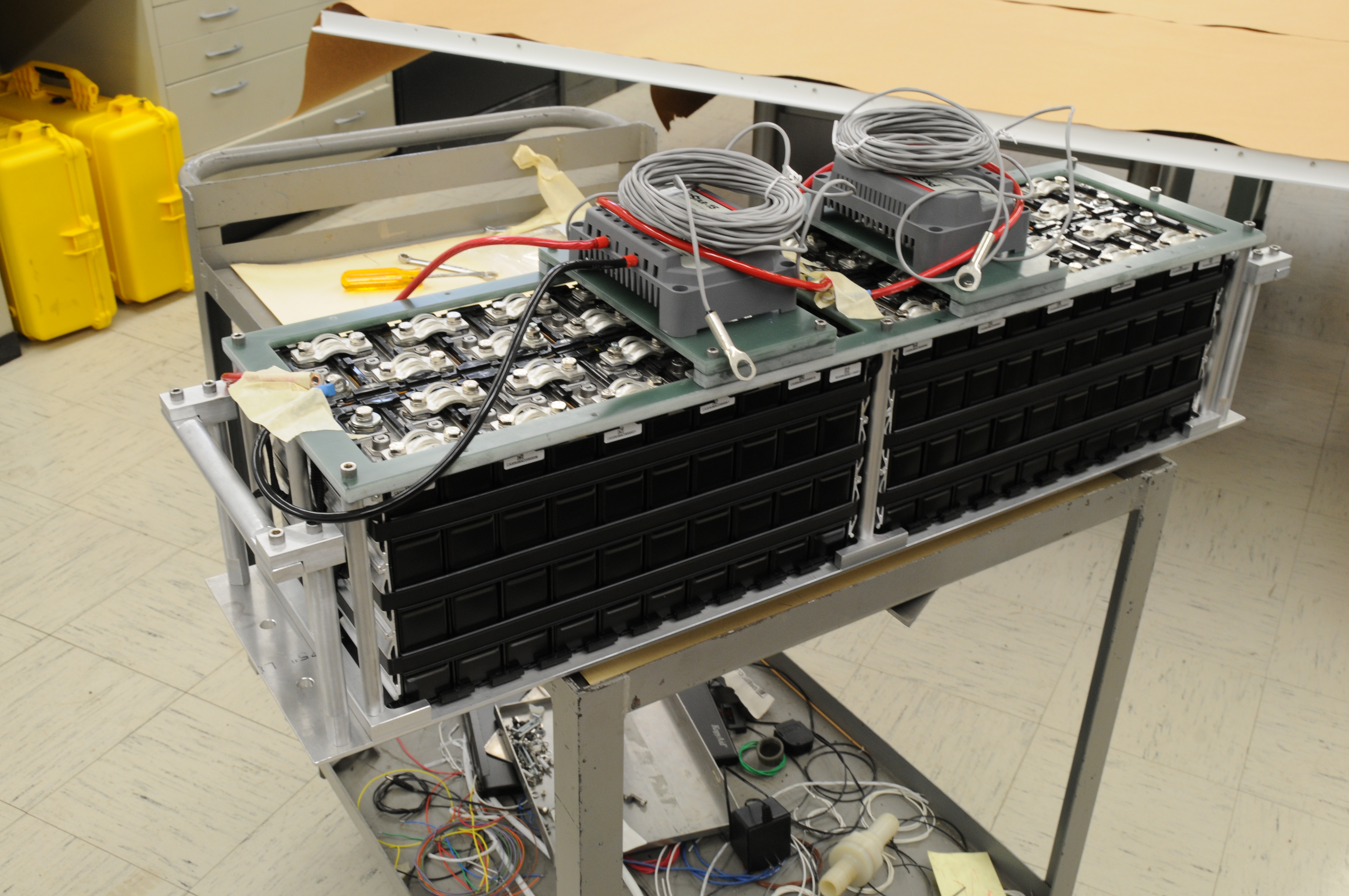 50 Battery assembly with controllers and handles |
 51 |
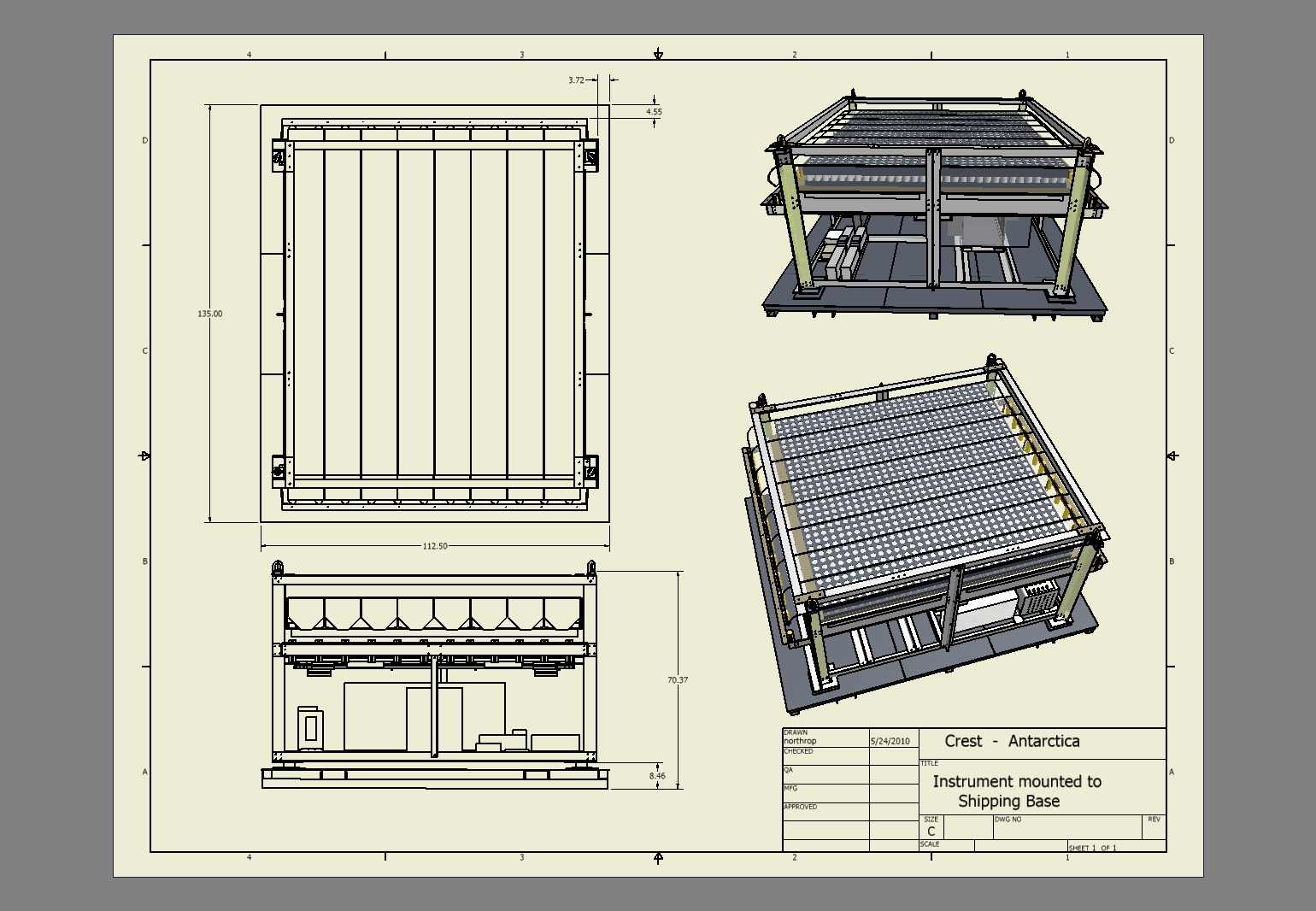
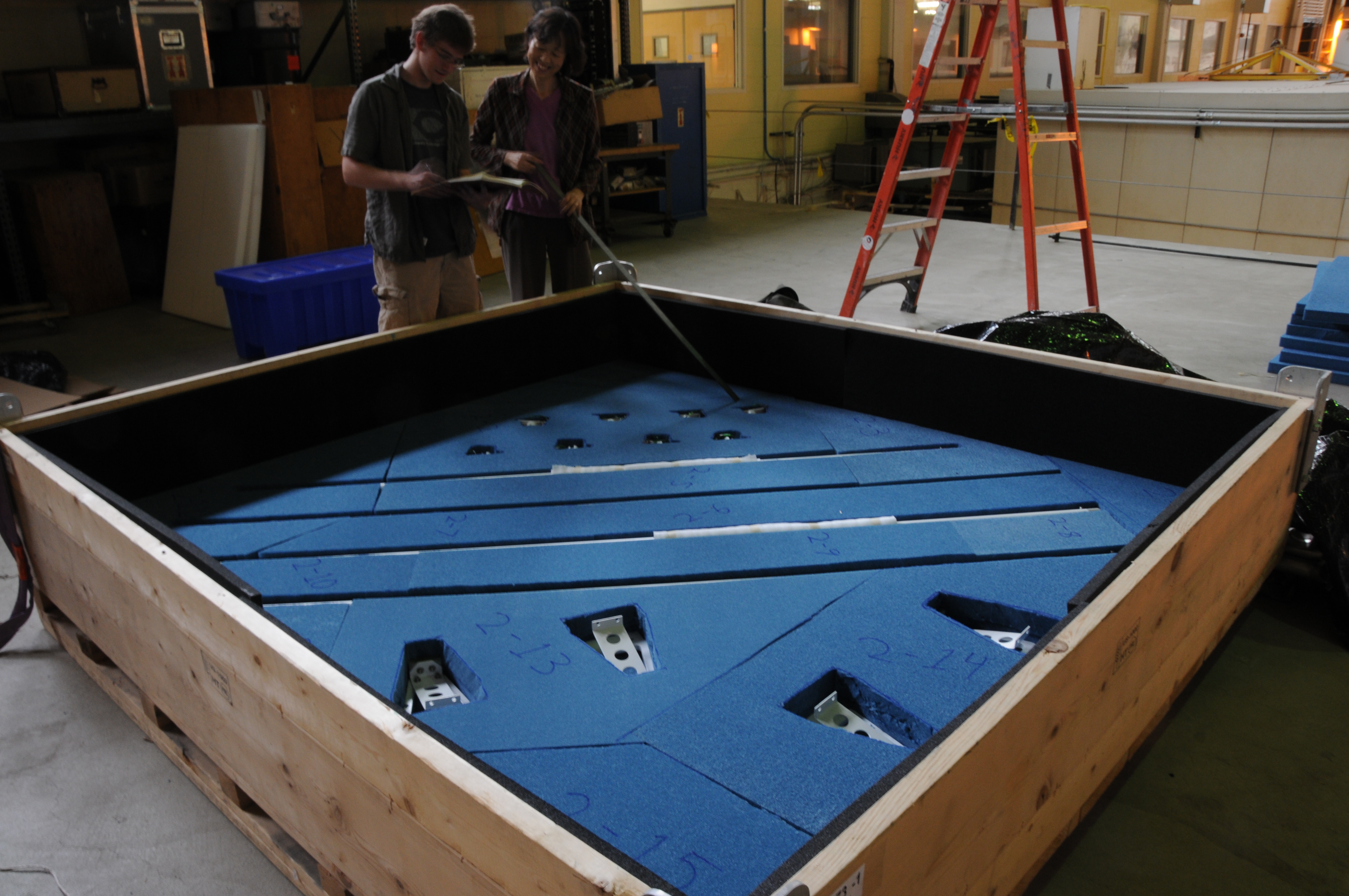
 52 |
 53 |
 54 |
 55 |
 56 |
 57 |
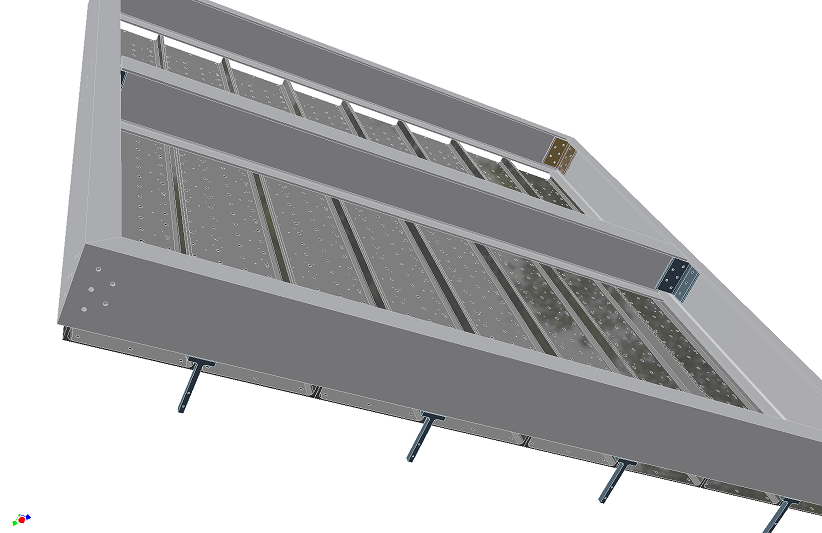 58 Bottom view of platform |
 59 |
 60 |
 61 |
 62 |
 63 |
 64 |
 65 |
 66 |
 67 |
 68 |
 69 Scott Wakely and Nahee Park checking power panel |
 70 |
 71 |
 72 |
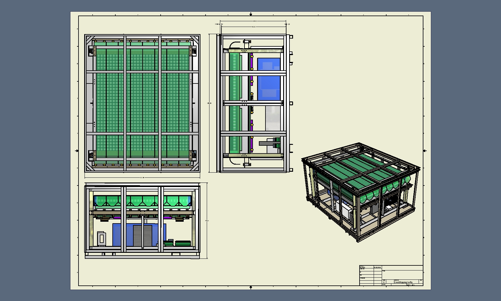
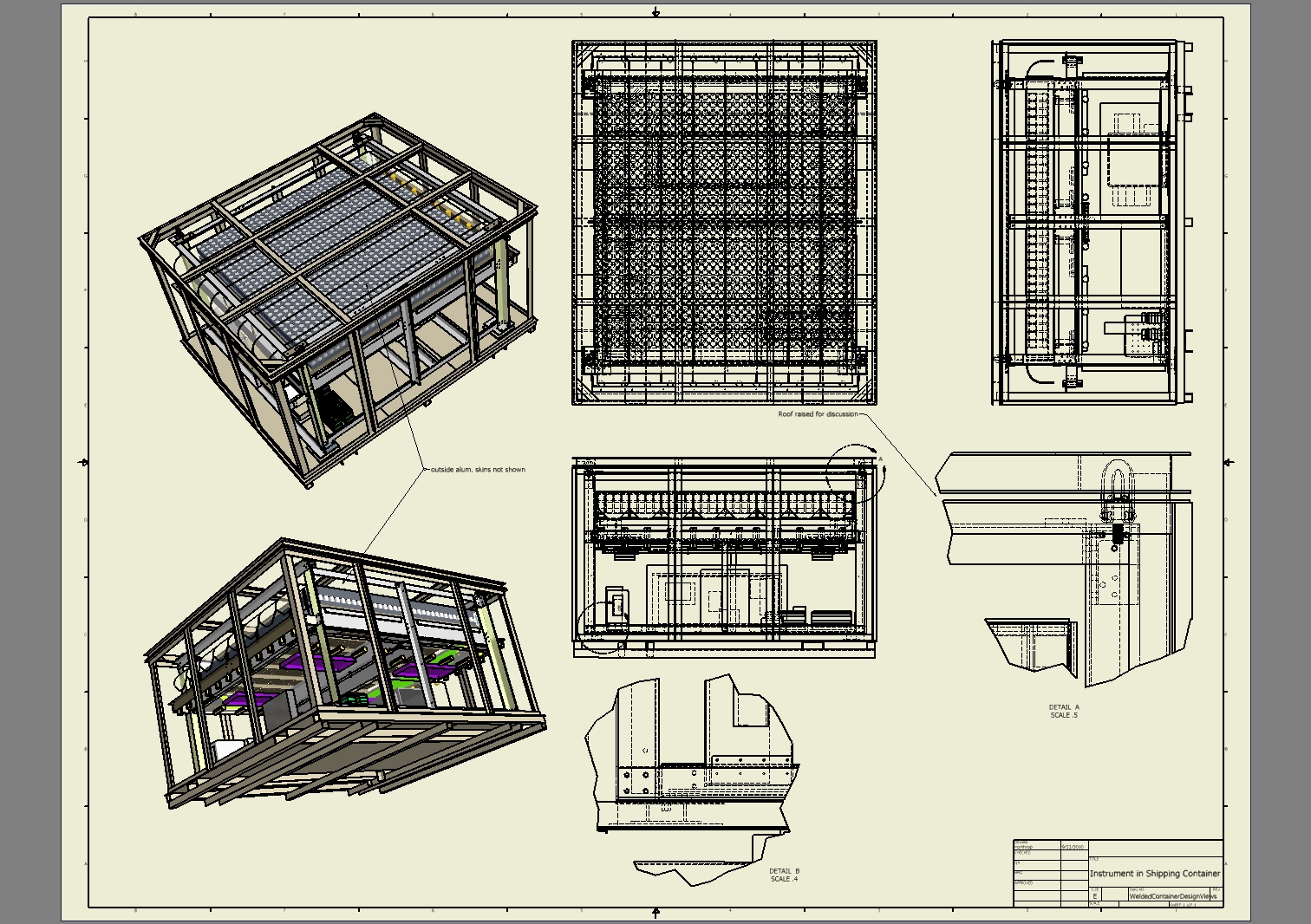
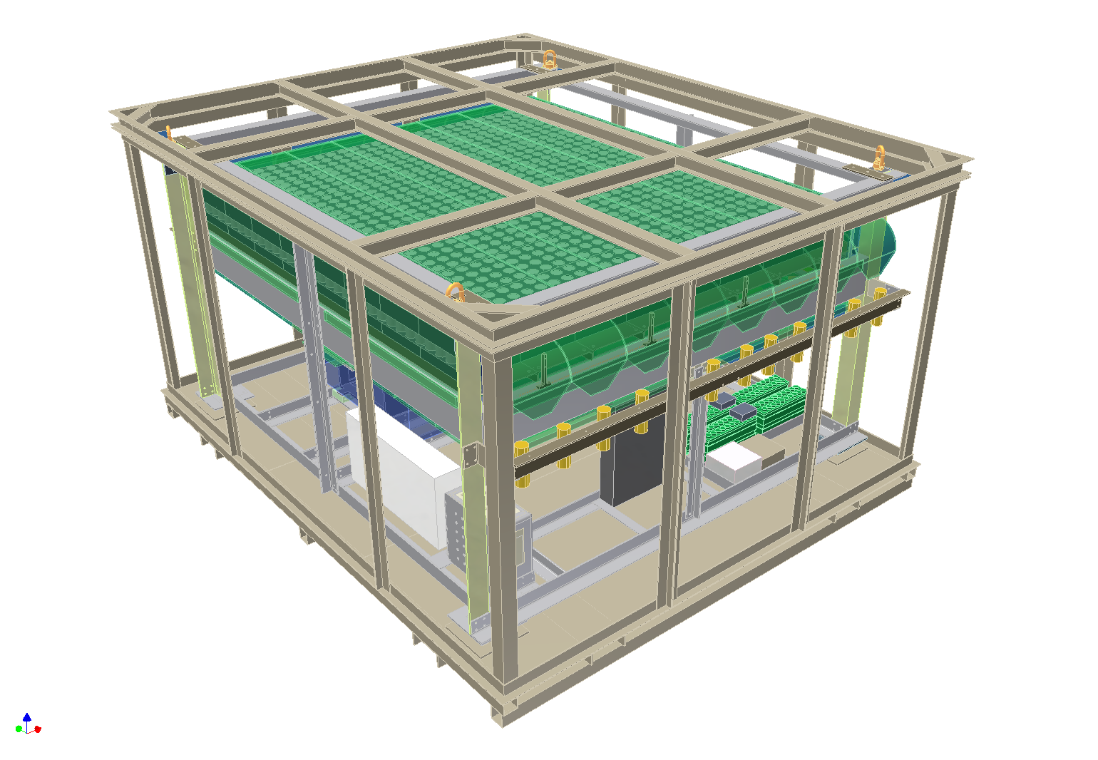 73 Crest instrument in shipping container |
 74 |
 75 |
 76 |
 77 |
 78 |
 79 |
 80 |
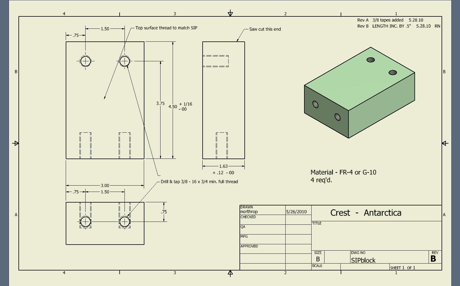
 81 SIP support and isolation G-10 blocks |
 82 |
 83 |
 84 |
 85 |
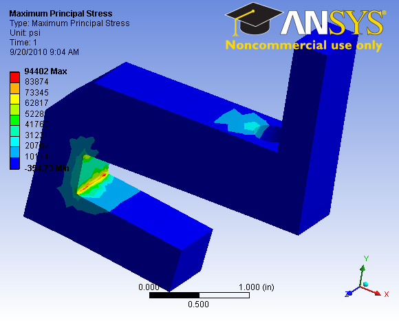
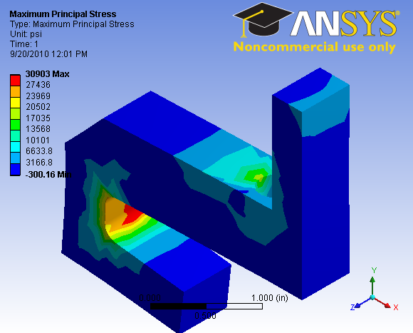
 86 |
 87 |
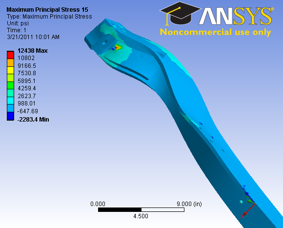
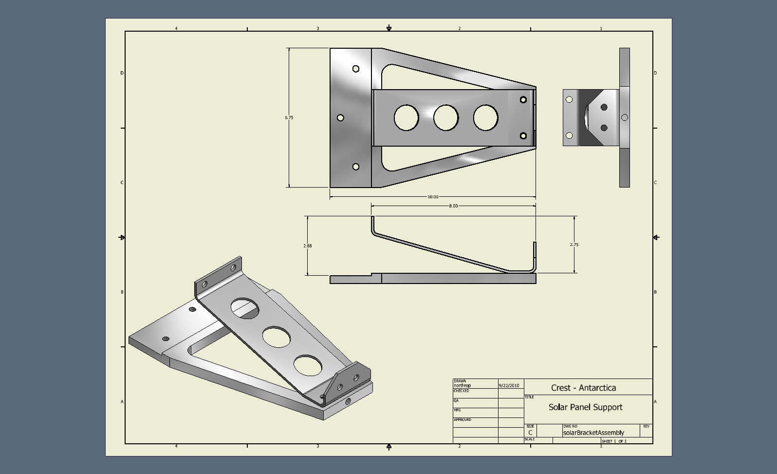
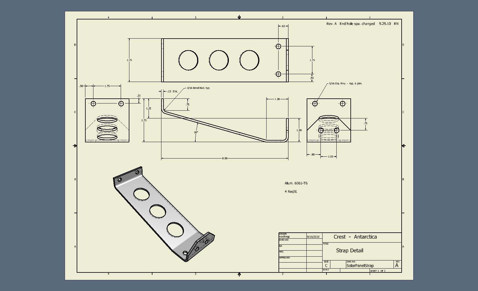
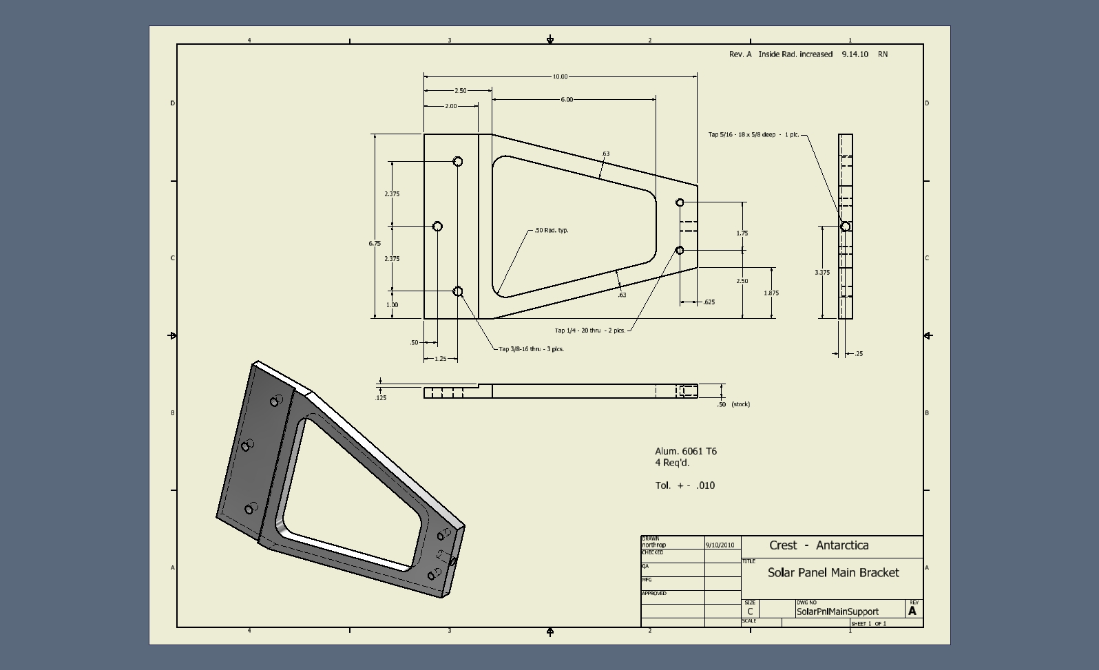
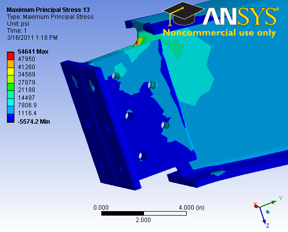
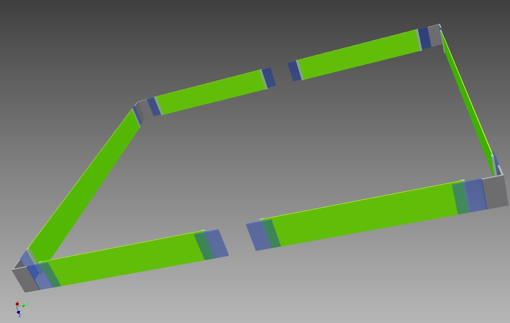
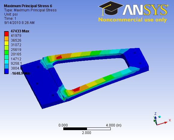 88 Solar panel bracket analysis before top strap added |
 89 |
 90 |
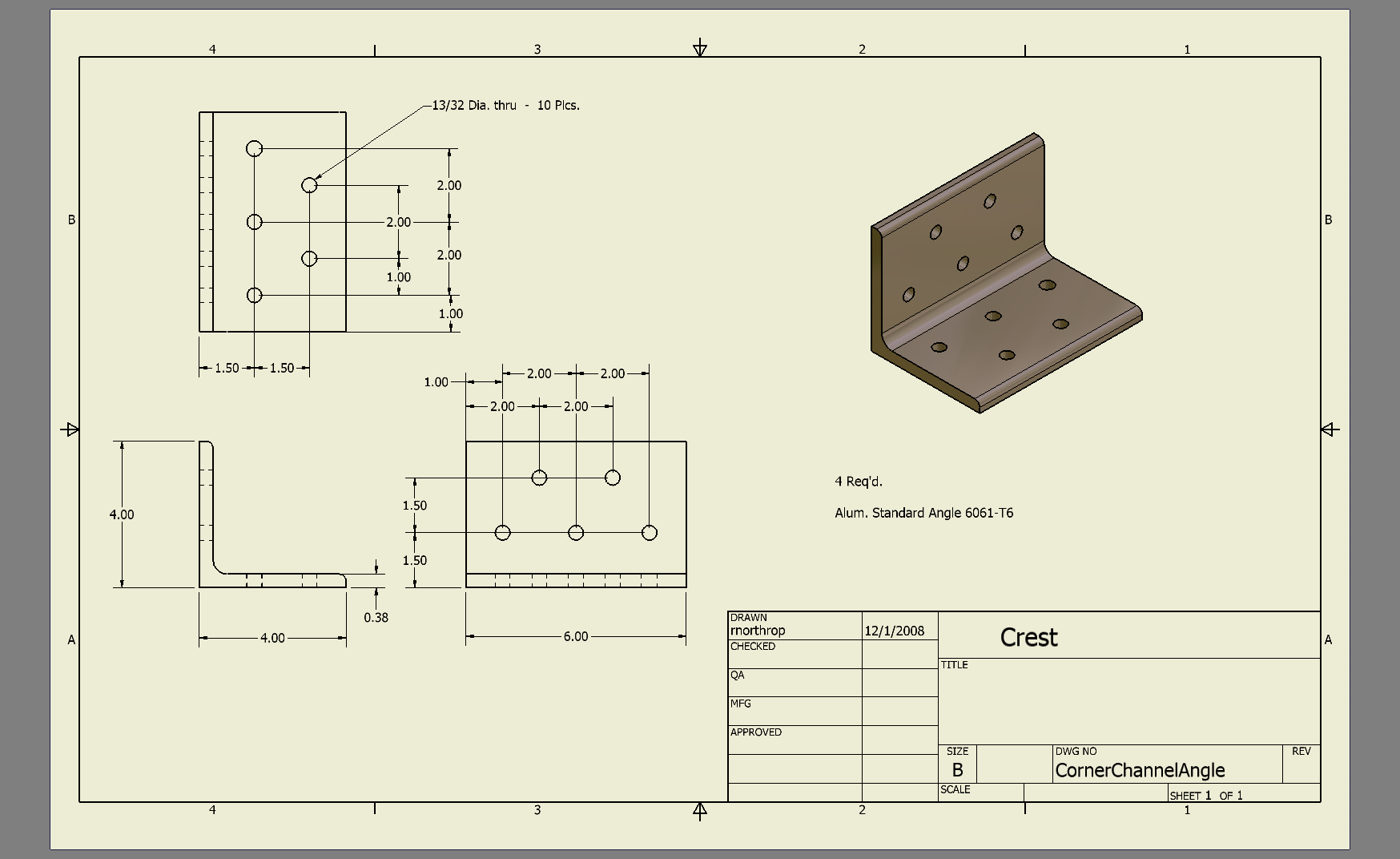
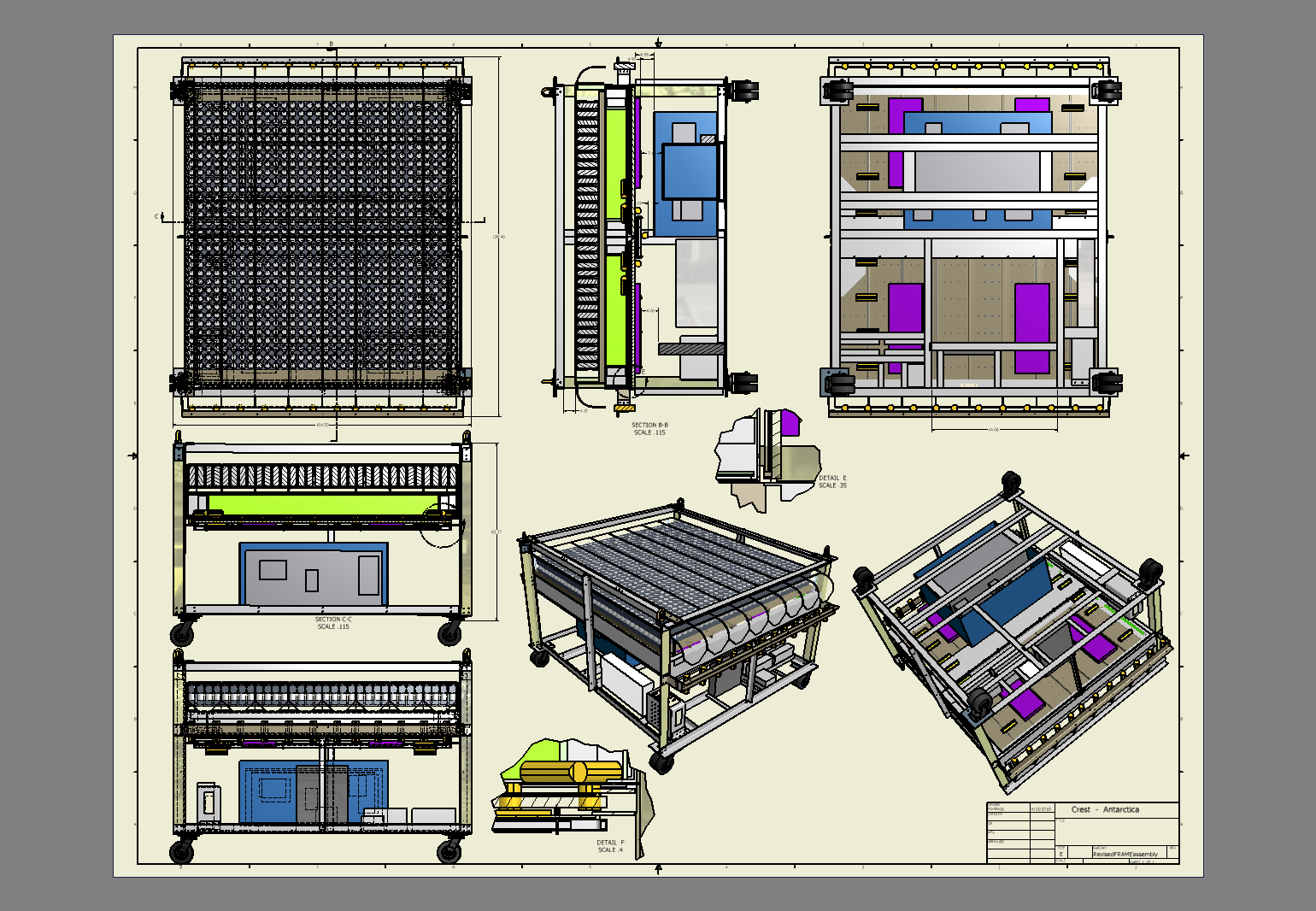
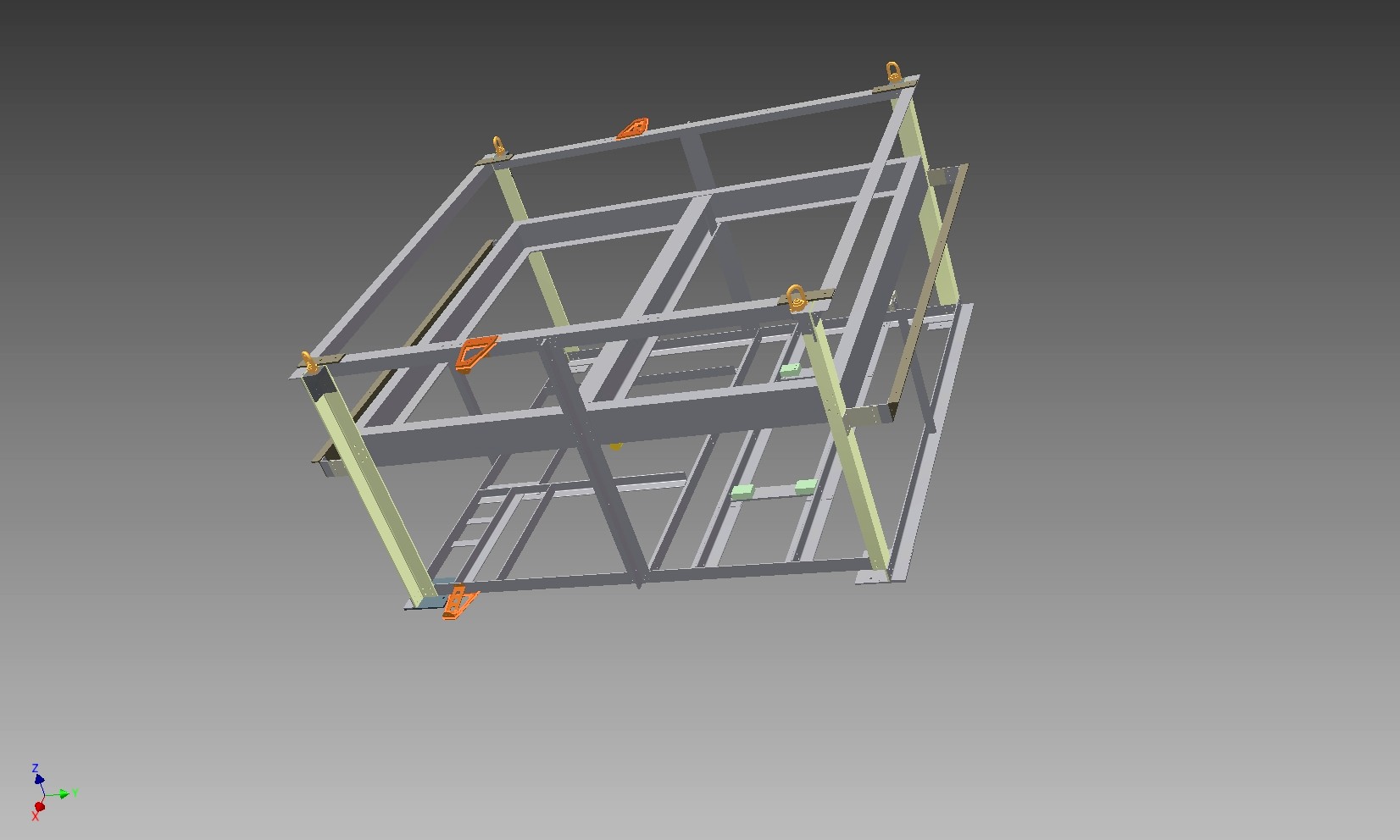
 91 |
 92 |
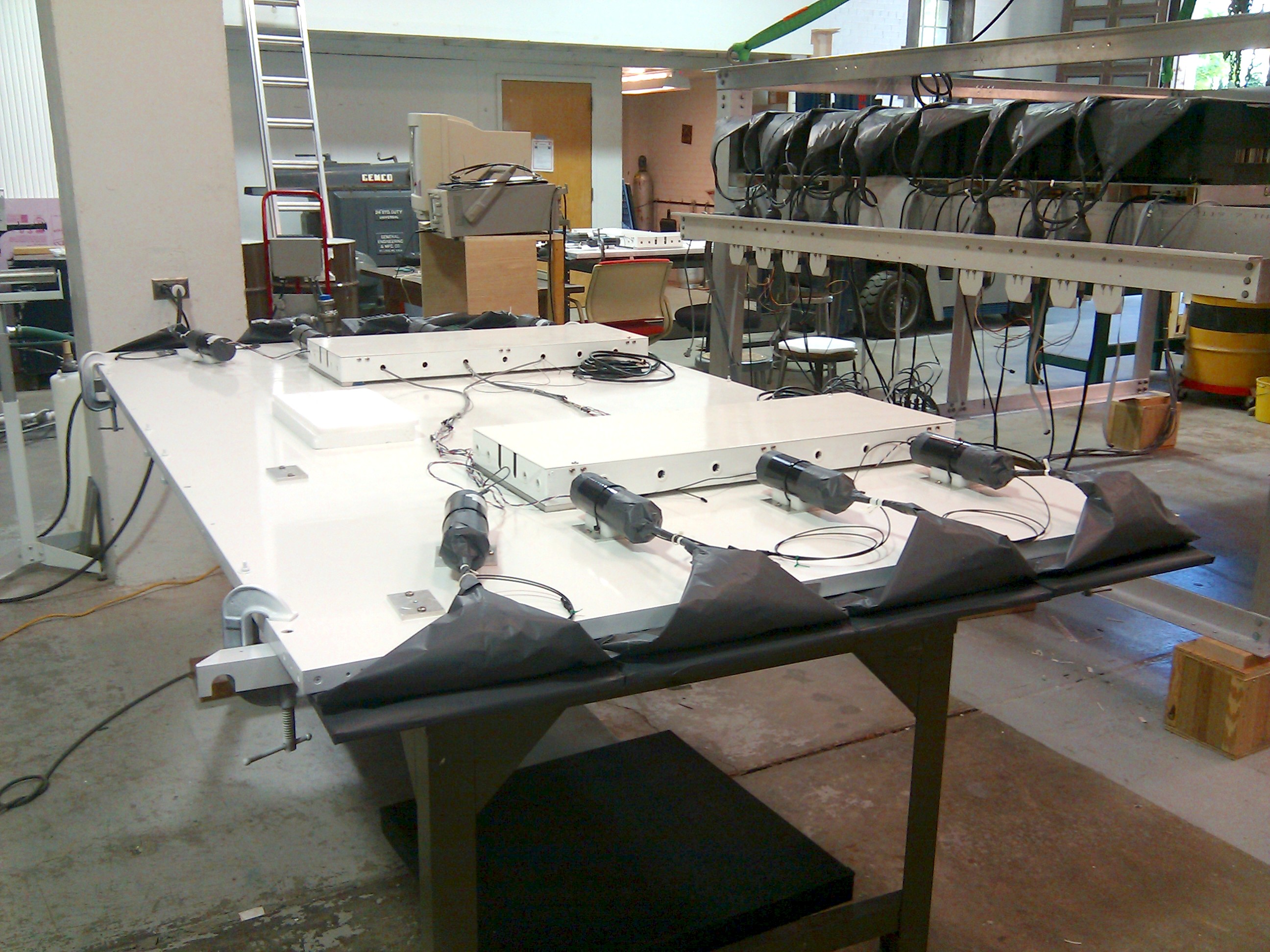
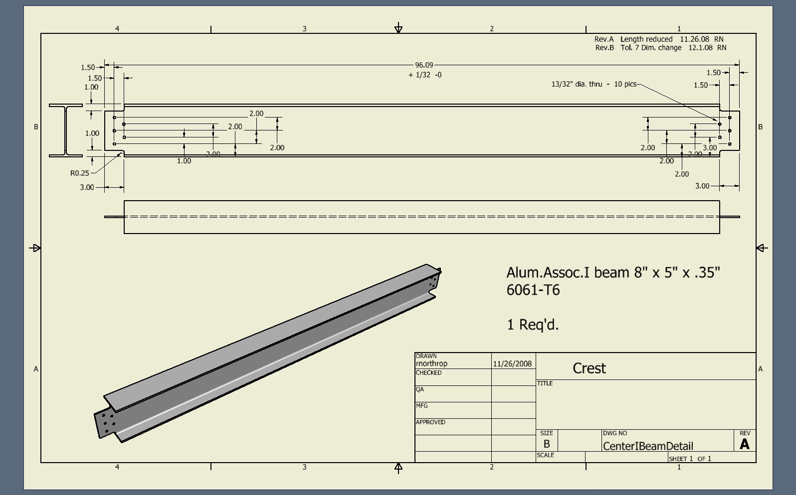
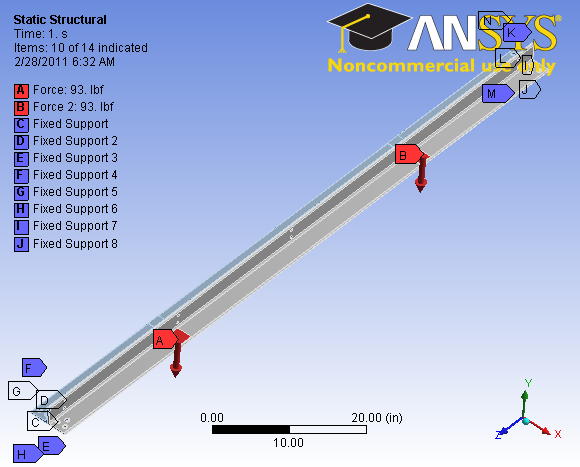
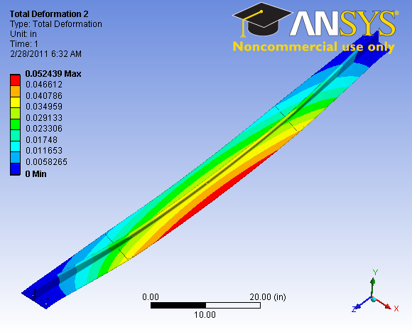
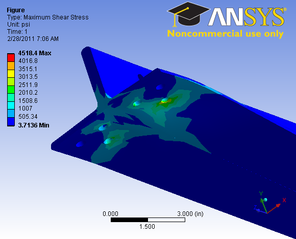
 93 Center beam end stress concentration before compression blocks added |
 94 |
 95 |
 96 |
 97 |
 98 |
 99 |
 100 |
 101 |
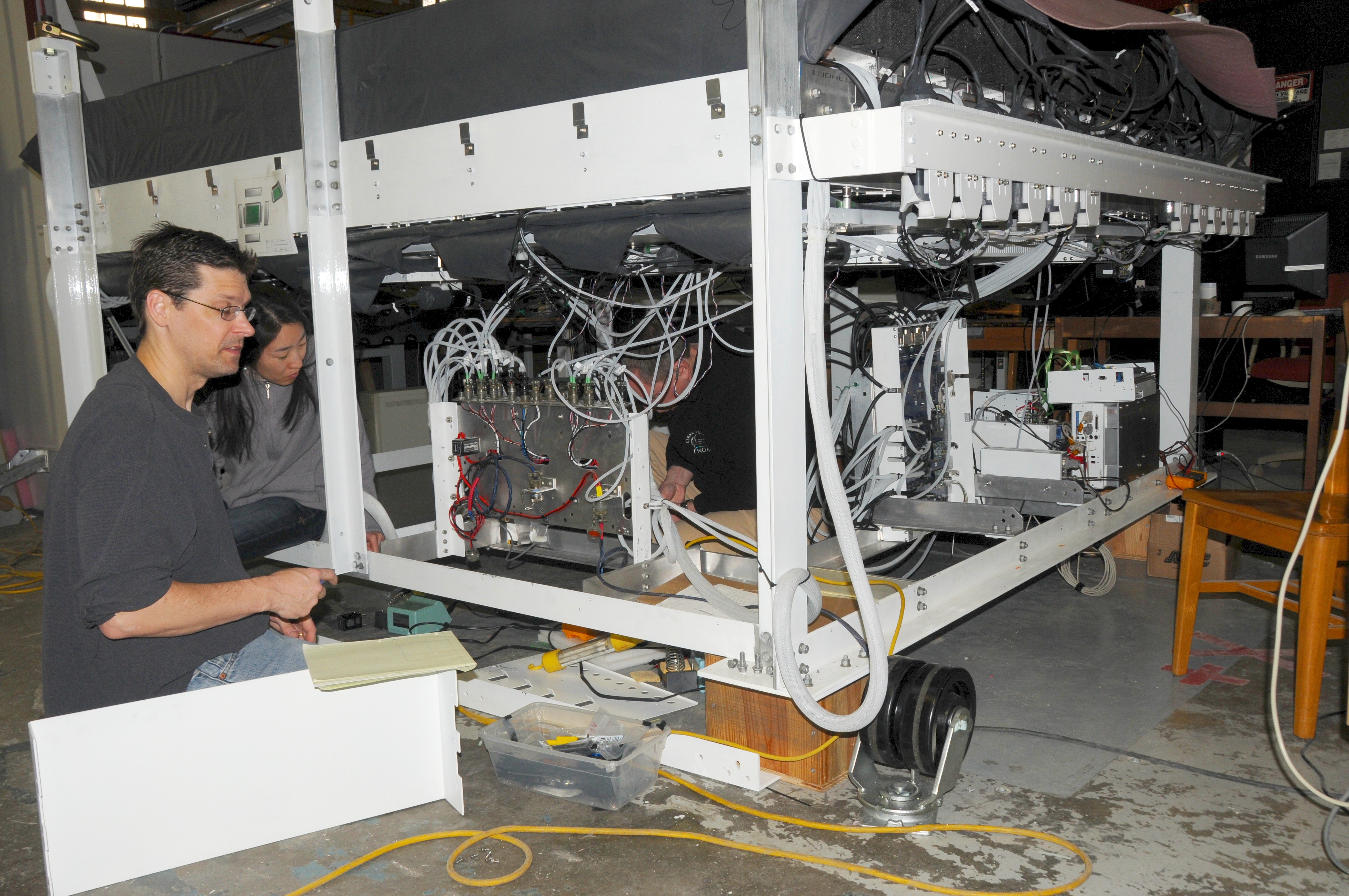
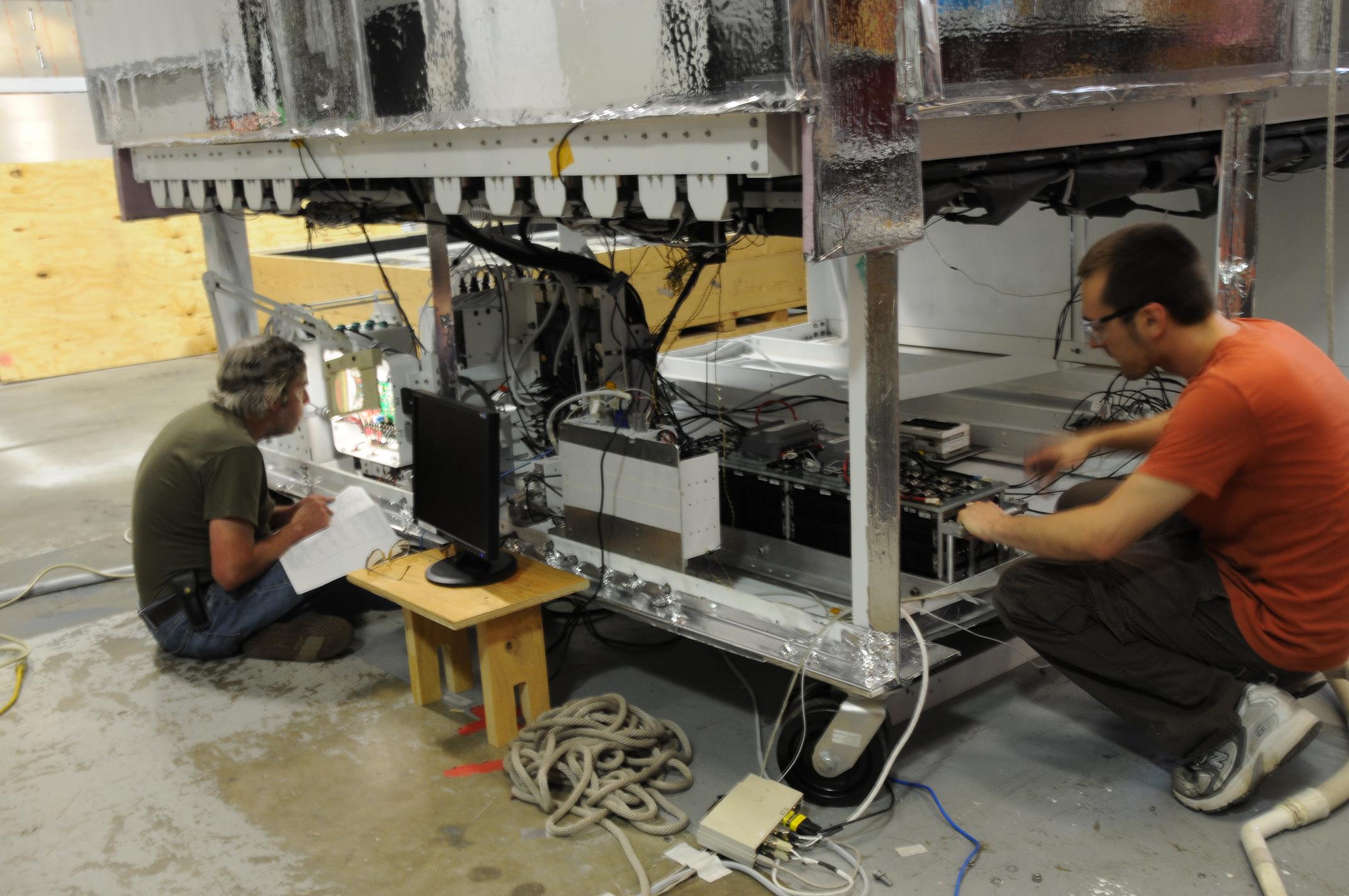 102 Mike Lang and Alex Shroyer working on lower section electronics |
 103 |
 104 First solar panel testing at The University of Chicago |
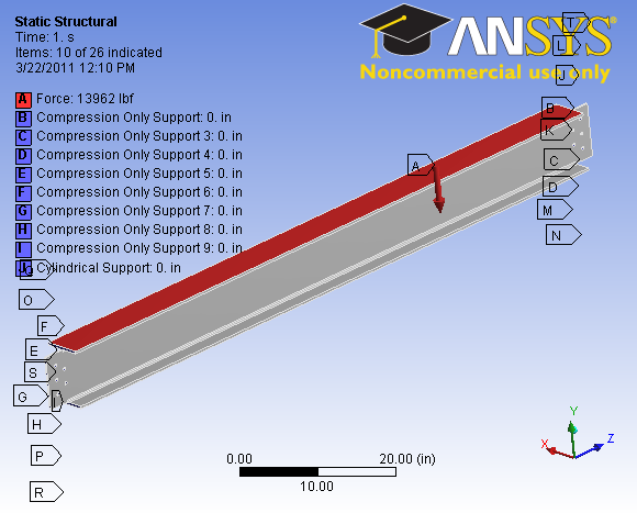
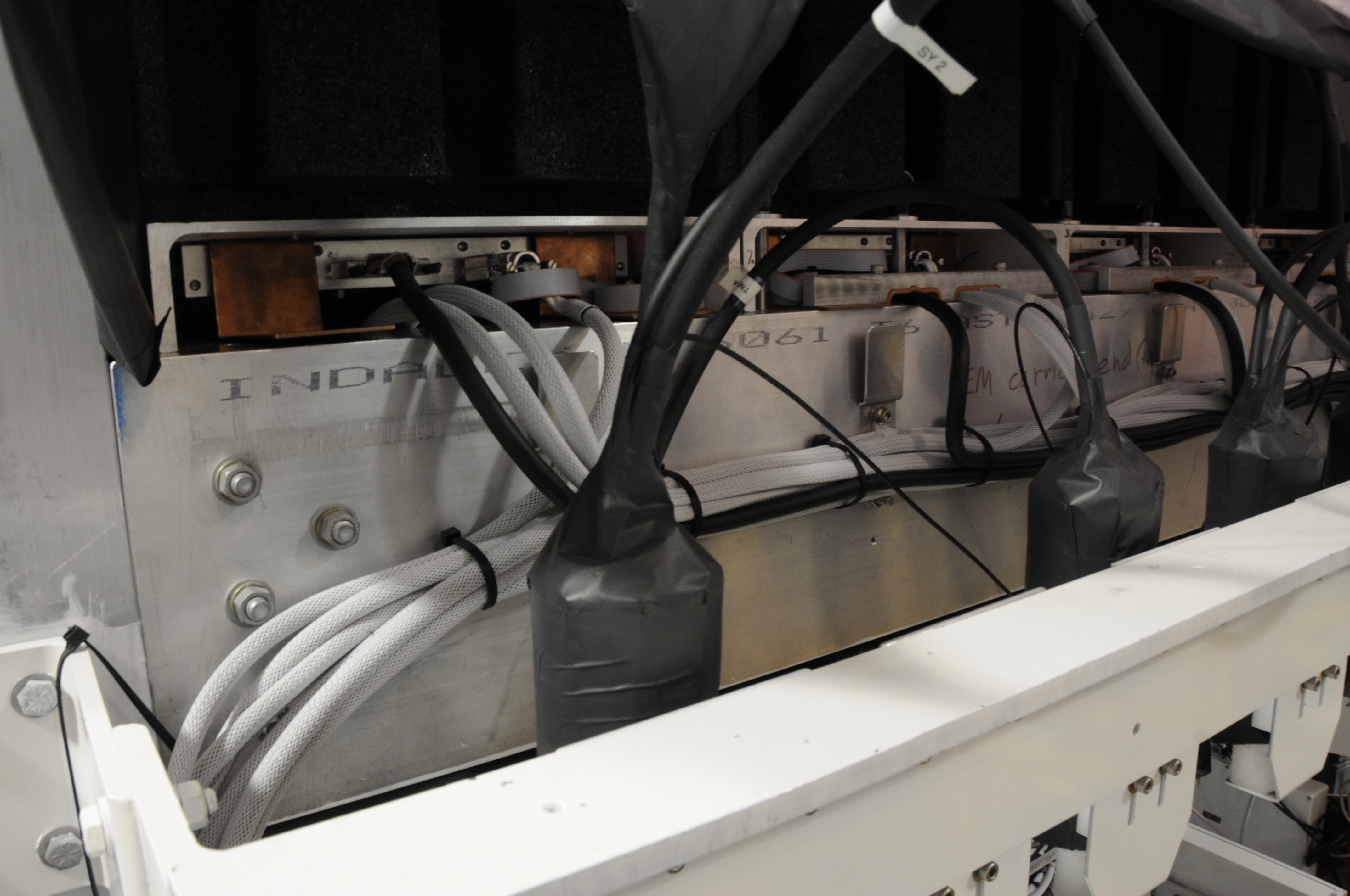 105 Channel end cable clamps and heat straps |
 106 Adam Brozynsli and Lin Zhou working on solar panel packing |
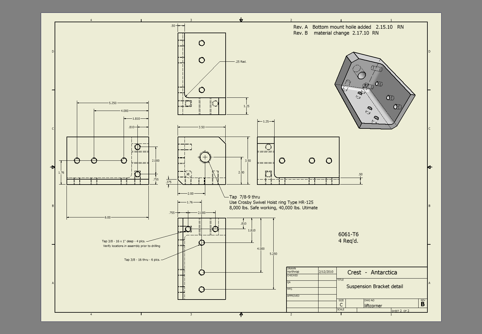
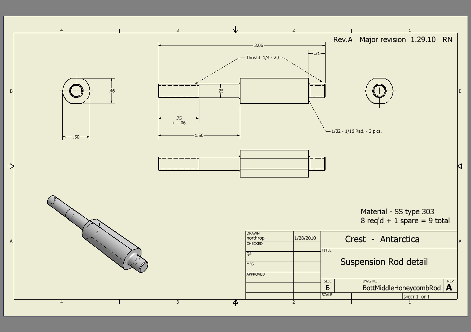
 107 Channel mount nut stress before large radius added |
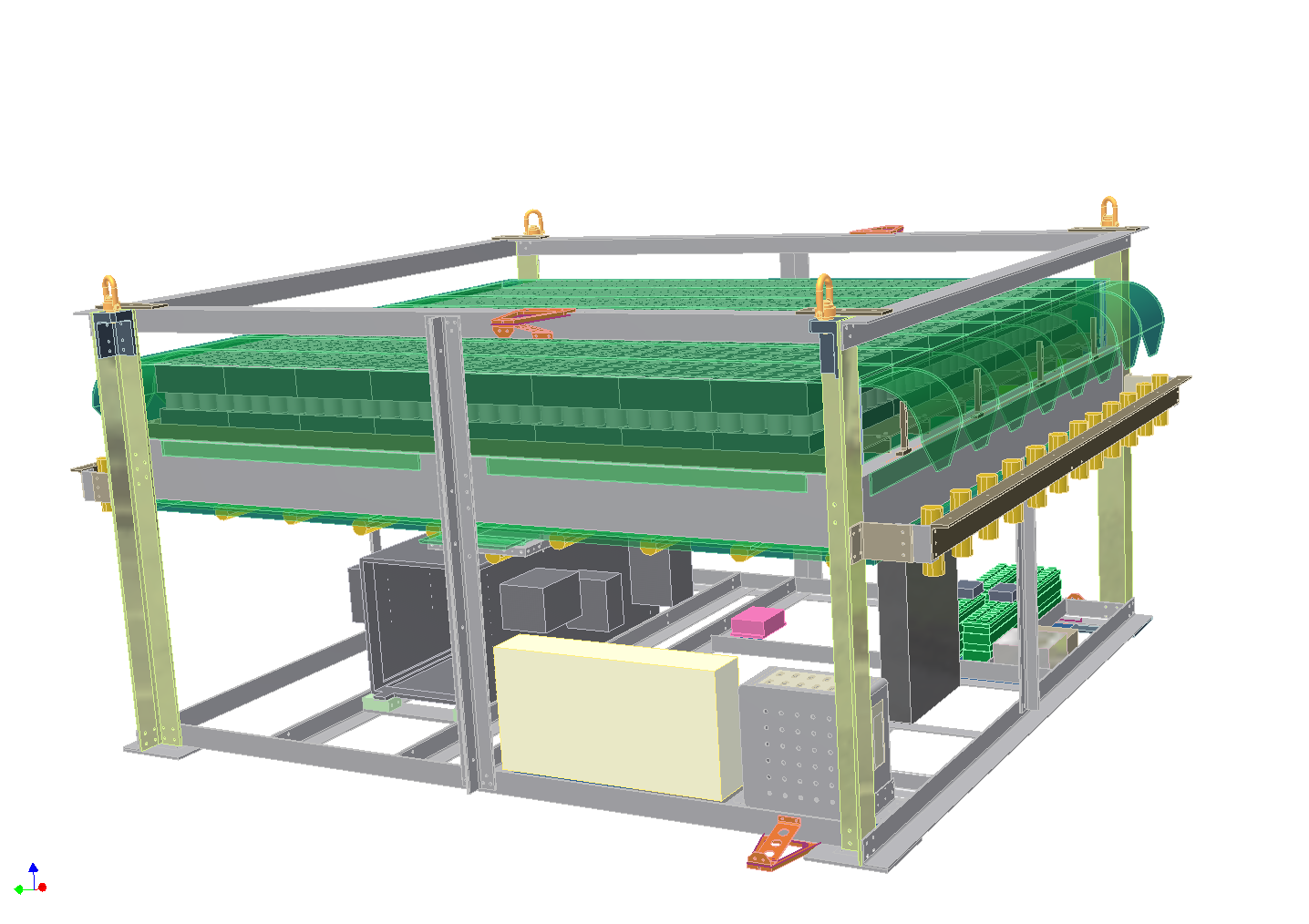 108 |
 109 |
 110 |
 111 Bottom veto support honeycomb closeout during construction |
 112 PCU main structure parts |
 113 Side top vetos |
 114 Inside veto assembly |
 115 Solar panels being assembled at The University of Chicago |
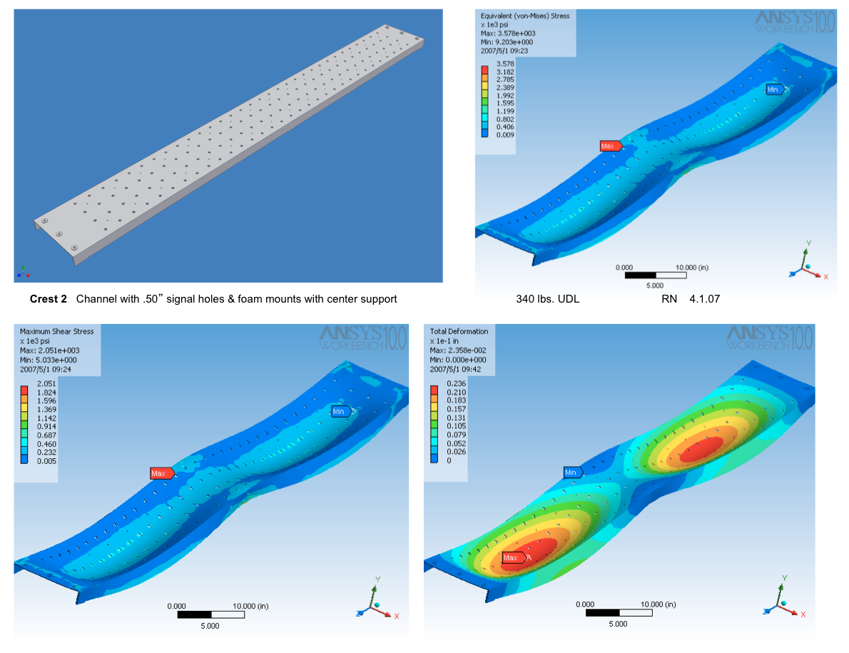 116 Channel study small holes |
 117 117 |
 118 118 |
 119 119 |
 120 120 |
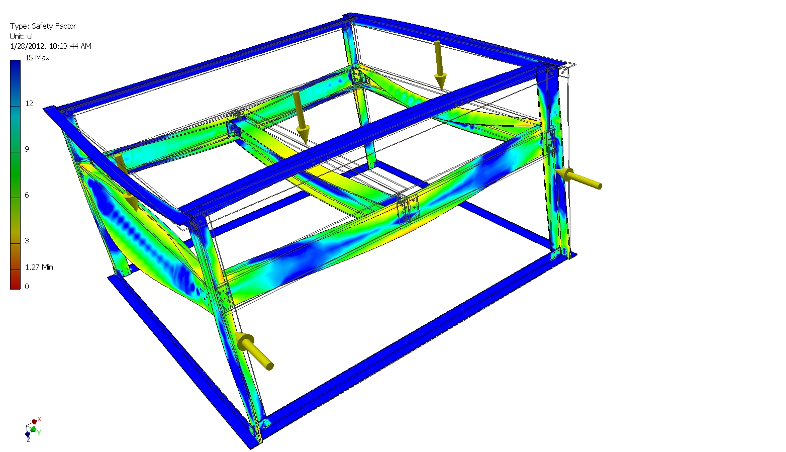
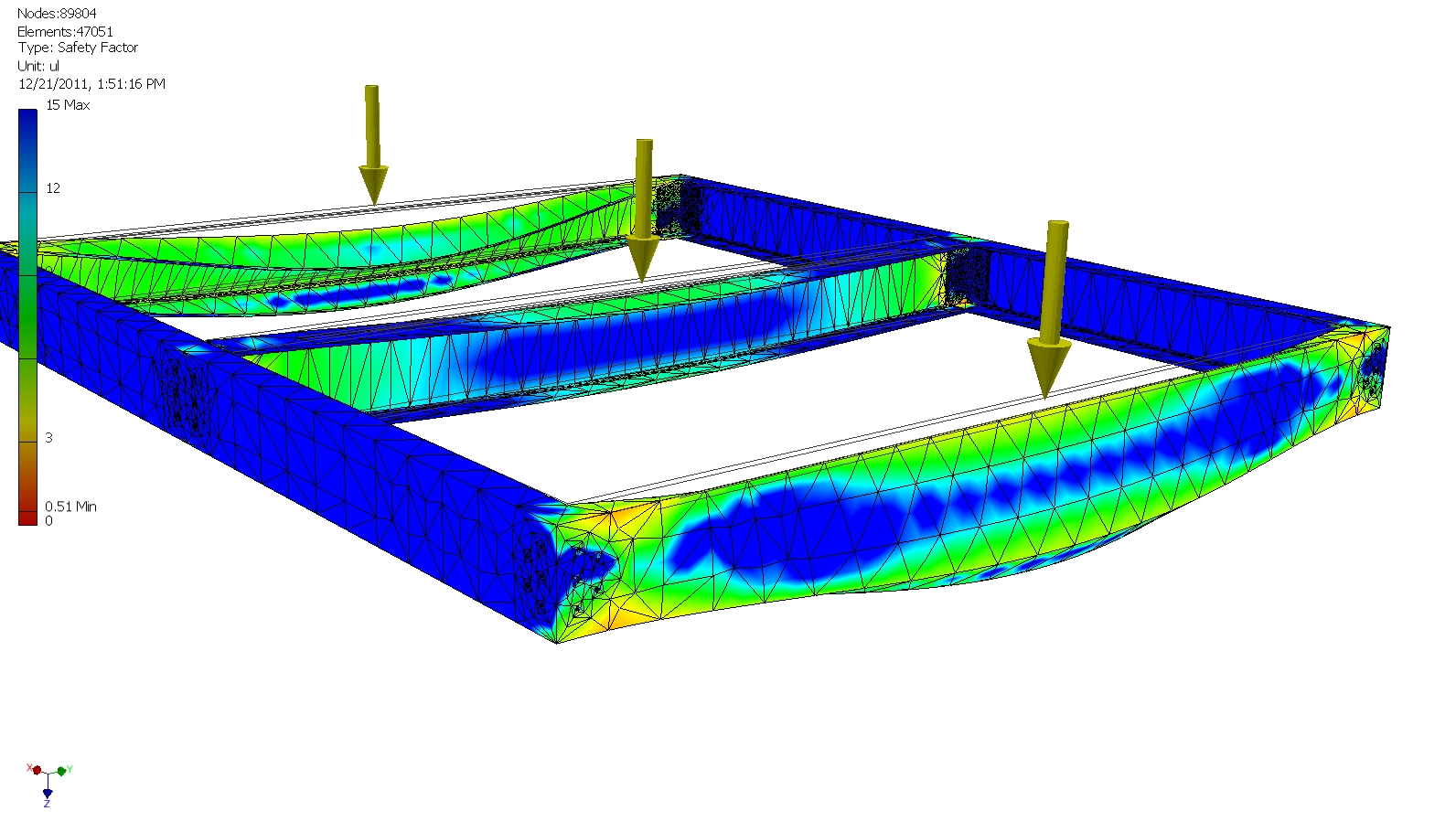 121 Gondola Platform under 30,000 lb. UDL load on center I beam & parallel outside channels |
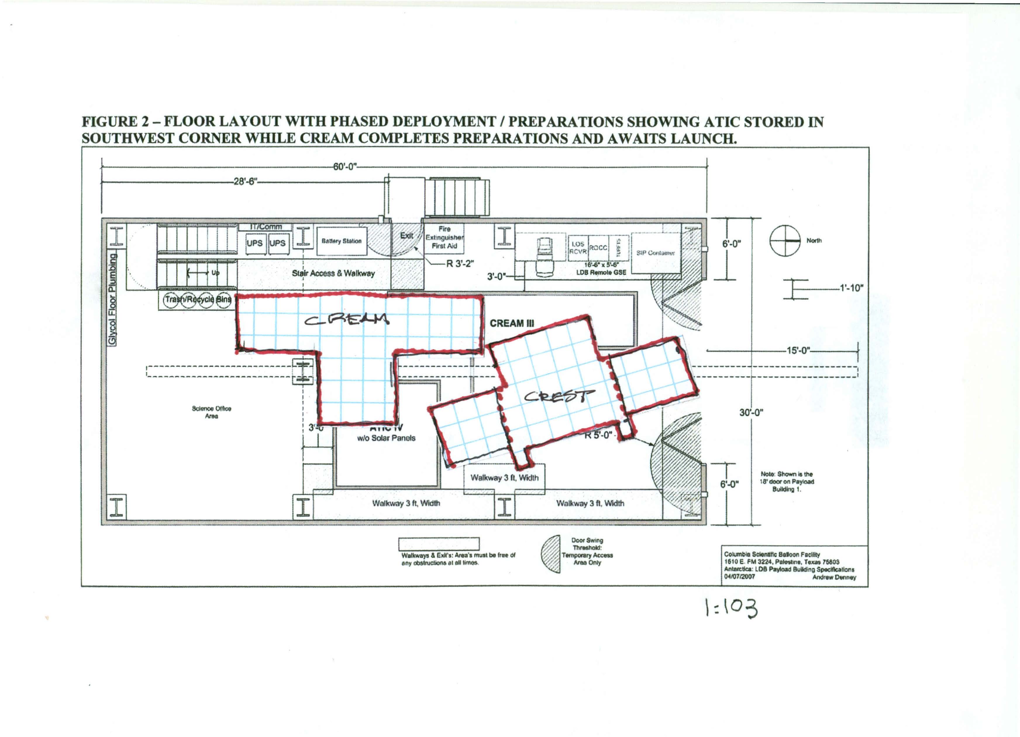
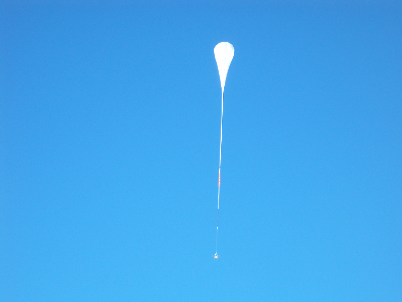
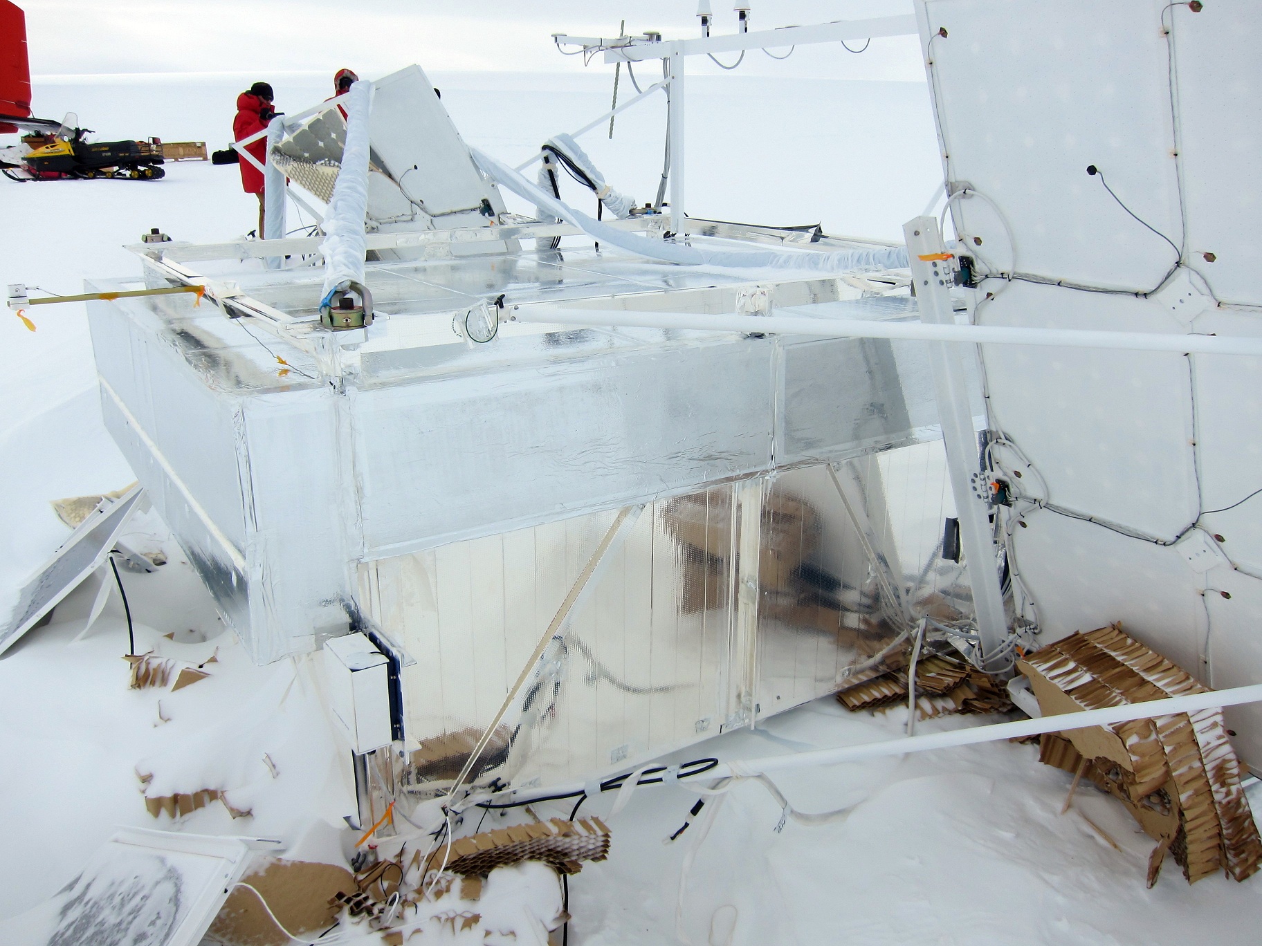
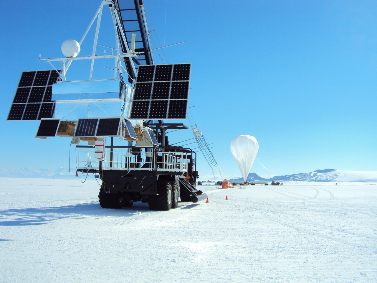 122 Crest/Antarctica Christmas eve launch |
 123 |
 124 Crest flight path – 10.5 day duration |
 125 Additional side loading of 5,000 lbs. (each corner) with addition of 5000 lb. side loading |
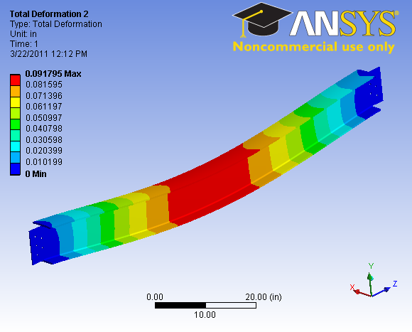
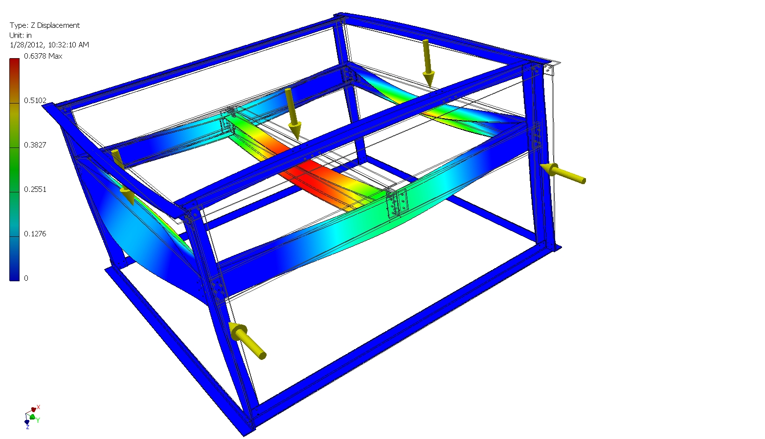 126 Center beam deflection under 10 G loading |
 127 |
 128 |
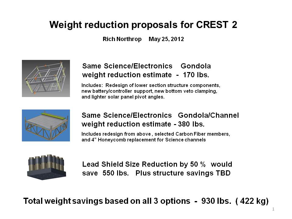
 129 Early CREST concept revisited for CREST 2. This design would eliminate material under the detector |
 130 |
 131 |
 132 |
 133 Prepared for May collaboration meeting |