July 21, 2005
Mircea Bogdan
In this example I used the following parts for one card:
1) P/N A263-4.8QT2 card-lock retainer - 2 pieces/card,
2) P/N F-109-R extractor - 1 piece/card,
3) P/N F-109-L extractor - 1 piece/card,
4) P/N 093-187 pin - 2 pieces/card,
5) Custom Aluminum strips - 0.063" thick - 4 pieces/card,
6) 2-56 flat head screw - 4 pieces/card.
Parts 1,...,4 are from Calmark Corporation.
Note 1: With the 0.063" thick PCB, the solder side strip has to be
0.063" thick. The component side strip can be diferent that 0.063", if
a different retainer is used. The gap in the card cage is 0.525".
Note 2: The PCB holes for the extractors are placed as per ANSI/VITA
1-1994 (.106" diameter, with centers .217" from the sides and .140" from
the front of PCB).
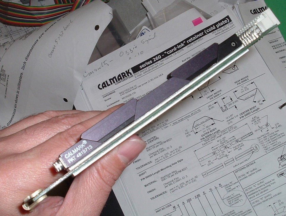
Side view of card; see above mentioned parts (except pins and screws) here:
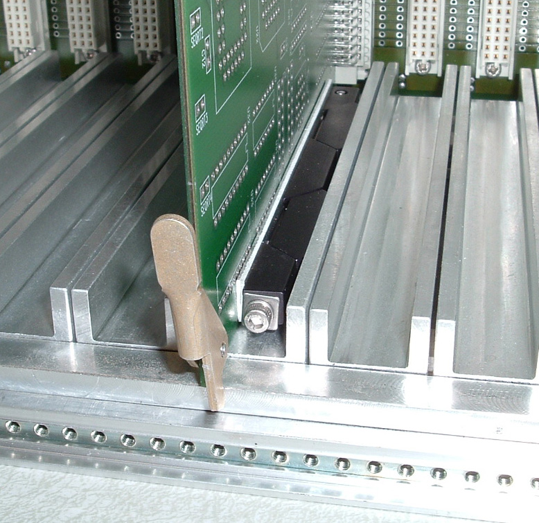
Front right view; see extractor, pin, card-lock retainer and componenet-side aluminum strip here:
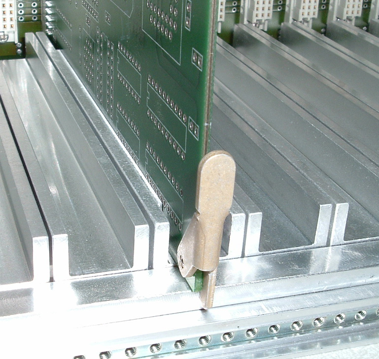
Front left view; see extractor, pin and solder side strip here:
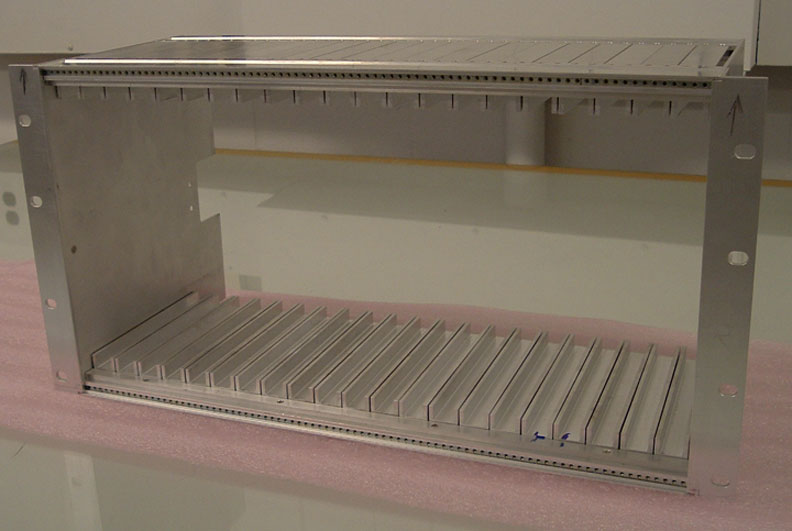
In this picture the Electronics Box is placed upside down on a horizontal
table.
See height of Electronics Box with a 1.5" wide SAB:

This is a picture of the Electronics Box only: