April 19, 2007
Mircea Bogdan
Performed breadbord functional testing for one single Preamp/Shaper/Driver
channel, to be used in the 14-Bit, 125 MHz ADC Board.
In this example I used the following Preamp/Shaper/Driver
Schematic.
These tests are preliminary.
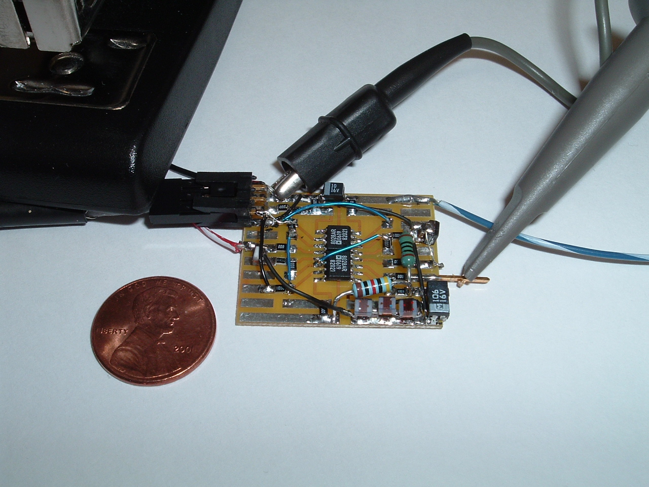
The picture below presents the breadboard implementation. The ADC Driver U3 (AD8139) not included.
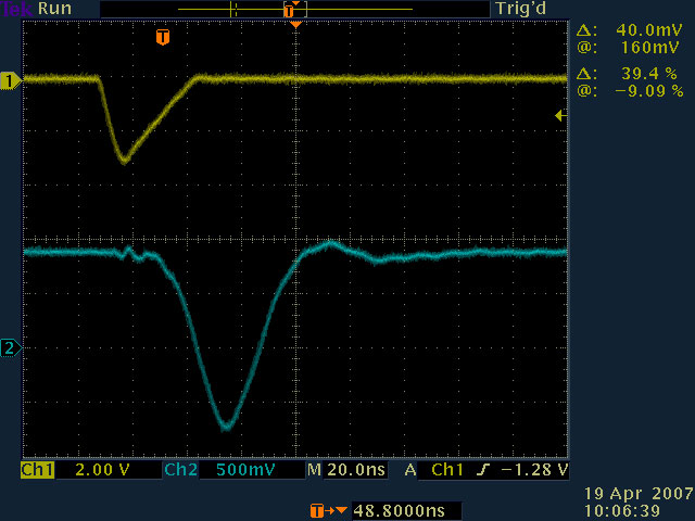
This picture presents:
- the input signal (in yellow), negative pulse from the PMT; generated
here with a LeCroy 9210 generator;
- the differential amplifier output signal U2-7(in blue); this pulse
goes to the ADC driver implemented with an AD8139.
The circuit gain can be adjusted by replacing R1, R2, R11, R13.
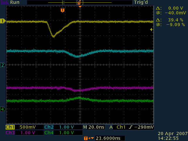
This picture presents:
- the input signal (in yellow), negative pulse from the PMT; generated
here with a LeCroy 9210 generator;
- the differential amplifier output signal U2-7(in blue); this pulse
goes to the ADC driver implemented with an AD8139;
- the ADC Driver U3 outputs: U3-4 OUTp (in red), U3-5 OUTn (in green).
Channels 3 and 4, in this picture, show the required input swing
for the ADC chip, in order to achieve full dinamic range.
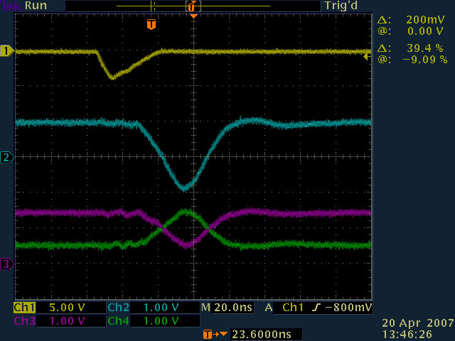
This picture presents the same signals, with a smaller input pulse.