OFC1-OFC2 - 5Gbps Transceiver Testing Instructions
Important ESD Protection Instructions
Warning, failure to follow ESD Precautions may lead to permanent damage of OFC2 Module
-
Never touch the OFC2 Module without being properly grounded, e.g. with a grounded wrist strap;
-
Never insert the Module in the VME crate when crate power is ON - No Hot Insertion;
-
Never plug a JTAG Blaster in any of the Module's headers when power is ON;
-
Plug Blaster in OFC2 Module first, and only after that plug the Blaster's USB end in the computer;
-
Never insert or remove QSFP Transceiver Modules or QSFP Pluggable Cables when power is ON;
-
When Module is removed from VME crate, it must be placed in ESD Static Shielding Bag immediately;
-
Do Not Remove Module from crate if ESD Bag is not handy;
-
Never move a Module that is not placed in ESD Bag, not even for 10ft (3m).
Instructions for testing the OFC1 with an OFC2 at 5Gbps
-
make sure the VME crate controller has the program vme7700 installed and funtional;
-
turn VME crate power off;
-
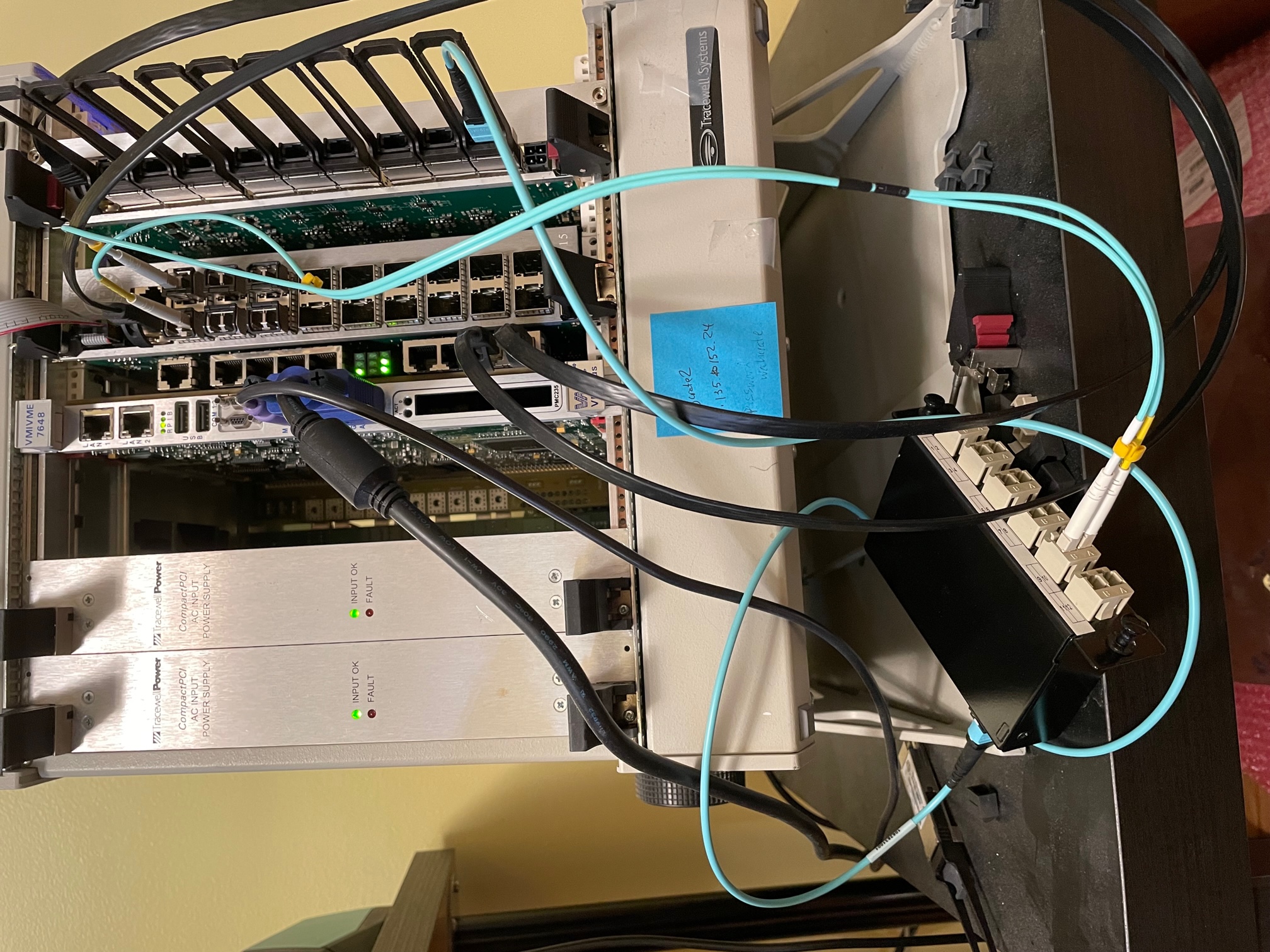
load OFC1 in slot 3 and OFC2 in slot 6
-
insert one USB Blaster to each module
-
set OFC1 and OFC2 to system clock, and provide clock with CAT5 cables from an MT board
-
-
power up crate
-
-
./vme7700 write 3 3c 1 - OFC1 in Test Mode
-
./vme7700 write 3 1c 1 - OFC1 Tx sends 0x3CBC
-
./vme7700 write 3 18 f - OFC1 Tx send in Control Mode
-
start OFC2-SignalTap with OFC2_S10_68
-
./vme7700 write 6 3c 1 - OFC2 in Test Mode
-
./vme7700 write 6 4000044 1 - OFC2 reset Rx - Observe SignalTap: the OFC2 will autoalign when receiving 0X3CBC in Control Mode
-
./vme7700 write 3 18 0 - OFC1 Tx sends 0x3CBC in Data Mode
-
./vme7700 write 3 1c 0 - OFC1 Tx sends counters in Data Mode
-
./vme7700 read 6 0 - read OFC2 serial number - this command is used only to trigger OFC2-SignalTap - observe counter on OFC2-SignalTap
-
repeat ./vme7700 read 6 0 and observe counters with OFC2-SignalTap
-
./vme7700 write 6 400000c 1 - OFC2 activate 64-bit error detection counter by writing 0x1 to register_3 - observe Reg_3 change value with OFC2-SignalTap
-
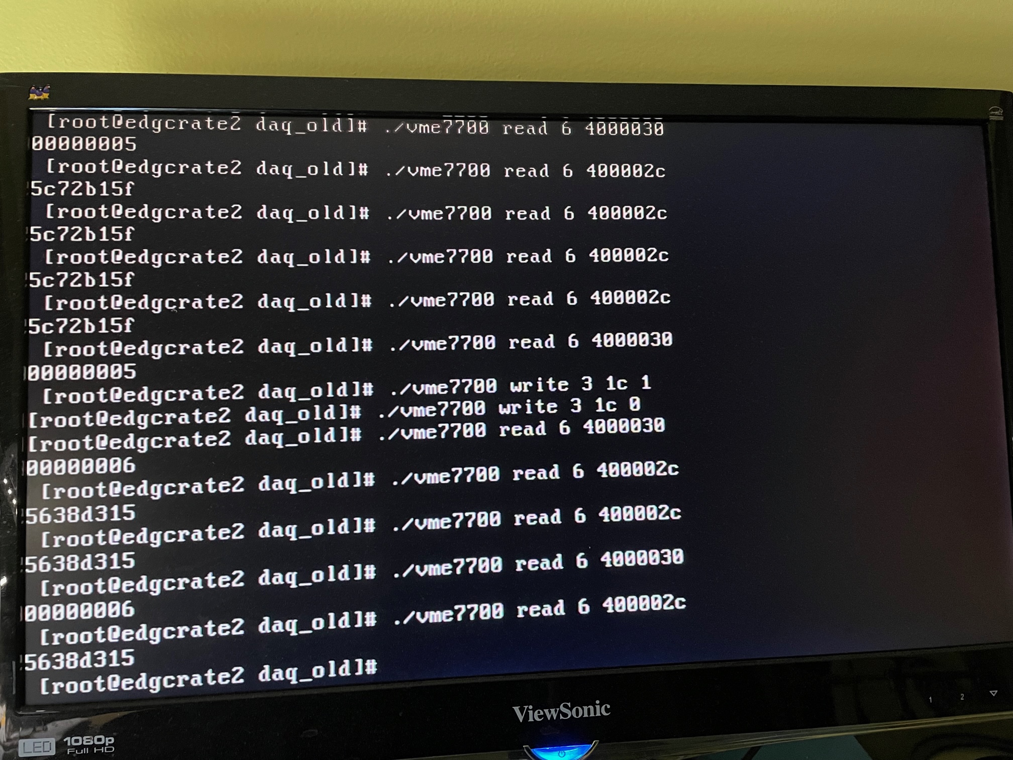
./vme7700 read 6 400002c - read error counter bits [31..0] - this value should be 0x0
-
./vme7700 read 6 4000030 - read error counter bits [63..32] - this value should be 0x0
-
./vme7700 write 3 1c 1 - OFC1 Tx sends 0x3CBC, now in data mode - this will force the error counter to record one error for each 8ns - observe errors and triggers with OFC2-SignalTap
-
./vme7700 write 3 1c 0 - OFC1 Tx sends counter in data mode again - errors should stop
-
./vme7700 read 6 0 - trigger OFC2-SignalTap - observe no more errors
-
./vme7700 read 6 400002c - read error counter bits [31..0] - this value should be something, depending on how long 0x3CBC was sent in data mode
-
./vme7700 read 6 4000030 - read error counter bits [63..32] - this value should be something, depending on how long 0x3CBC was sent in data mode
-
now the OFC1-Tx sends counters to OFC2-Rx and the error detector is active
-
repeat the above readings of the error counter several times - the values should stay the same, i.e. there are no more errors
-
wait as long as possible (hours?) and repeat readings above
-
to see that the error detector is still active force the Tx to send 0x3CBC in data mode again, to increase the error count, and then to send a counter again, to stop the errors
-
./vme7700 write 3 1c 1 - OFC1 Tx sends 0x3CBC, now in data mode - this will force the error counter to record one error for each 8ns - observe errors and triggers with OFC2-SignalTap
-
./vme7700 write 3 1c 0 - OFC1 Tx sends counter in data mode again - errors should stop
-
./vme7700 read 6 0 - trigger OFC2-SignalTap - observe no more errors
-
now reading the error counter again should return a different value, which should stay the same after successive readings.
-
For questions regarding this page contact
Mircea Bogdan.
bogdan@edg.uchicago.edu
Updated: April, 2022