The SVT GhostBuster Board
This board = VME + 3 x (SVT data format input => big programmable
chip => SVT output).
Schematics: top, in,
logic,
out,
l2out,
vme,
vmechip,
P0,
P1, P2,
power
Manufacturing info:
Specification.pdf
Assembly.pdf
Gerber_files.ZIP
BOM_file.XLS
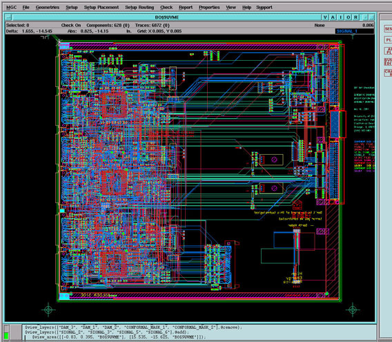
GhostBuster Layout as seen in the Mentor Graphics design environment:
For questions regarding this page contact Mircea Bogdan.
bogdan@impulse.uchicago.edu
Revised:12/12/02.