10-Pole Filter/Shaper Test
Card
Designed a Test Card with one
Preamp/Shaper/Driver
channel, to be used in the 14-Bit, 125 MHz ADC Board.
The schematic of the card is persented here: Preamp/Shaper/Driver
Schematic.
The layout of the card is persented here: Preamp/Shaper/Driver
Layout.
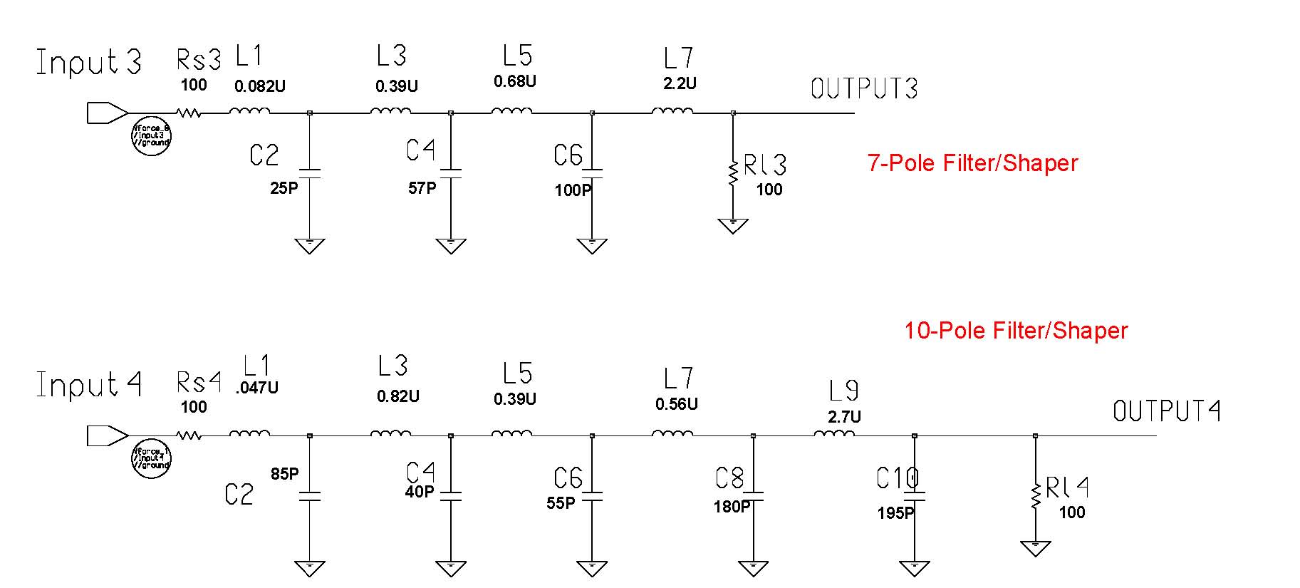
The Filter/Shaper configuration can be changed by replacing L1, C2,
L3, C4, L5, C6, L7, C8, L9, C10.
This picture below presents two different filter configurations (7-Pole
and 10-Pole) that were simulated, implemented on the Test Card, and
tested:
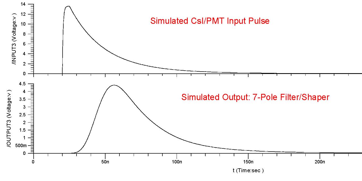
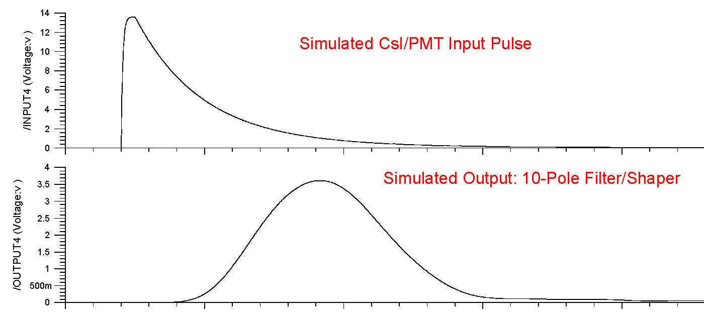
The pictures below persent simulation results for the two filter
configurations.
Simulation was performed with AccuSim by Mentor Graphics; the same
input pulse was used.
7-Pole Filter/Shaper:
10-Pole Filter/Shaper:
10-Pole
Scintillator/PMT Test
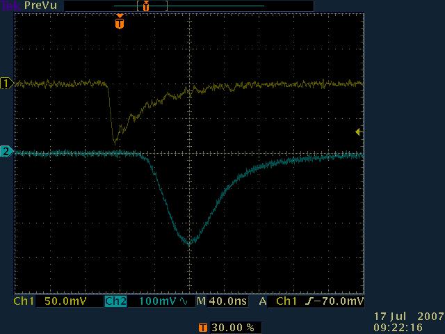
Performed a 10-Pole Shaper test using pulses from a
Scintillator/PMT module.
The Module consists of a crystal block (containing double-layered 8x8
LSO/LYSO crystals) coupled to an array of 2 by 2 photomultipler tubes
(PMTs). Each PMT is centered at a corner of the crystal block, and each
double-layer detection element is 2.1 × 2.1 × 20 mm^3 (the
individual
scintillator length is 10 mm) and the crystal pitch is 2.43 mm.
This picture presents the Shaper Test Card Input signal, coming from
the Scintillator/PMT Module (in yellow), and Output signal (in blue).
The scope sampled data are here: input,
output.
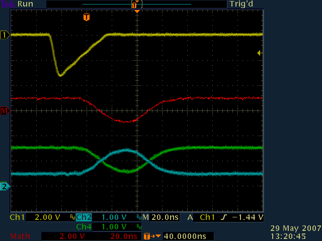
7-Pole Test
This picture presents a test on the same board, in the 7-Pole
configuration and with the gain decreased
by changing to: R3=R22=100Ohm.
- the input signal (in yellow), generated with a LeCroy 9210
generator;
- the differential output signal (Out1 and Out2 in green and red);
- the ADC Driver A)-52 outputs: OUTp (in bule), U3-5 OUTn (in green).
Channels 3 and 4, in this picture, show the required input swing
for the ADC chip, in order to achieve full dinamic range.
The scope calculated difference is shown in red.
The scope sampled data are here: input, output1, output2,
math.
For questions regarding this page contact
Mircea Bogdan.
bogdan@edg.uchicago.edu
Revised: July 18, 2007