
Questions, problems, comments, etc., contact Rich Northrop. (Change the AT to @ in his email address.)
CTA Camera Development - Mechanical (May 9, 2014 report) (pptx) (pdf)
CTA Camera Deveopment - Mechanical (Sept. 9, 2013 report) (pptx) (pdf)
CTA Camera Developement - Mechanical (May 28, 2013 report) (pptx) (pdf)
CTA Camera Development - Mechanical (Jan. 14, 2013 report) (pptx) (pdf)
CTA Camera Development - Mechanical (Oct. 25, 2012 report) (pptx) (pdf)
CTA Camera Development - Mechanical (Sept. 28, 2012 report) (pptx) (pdf)
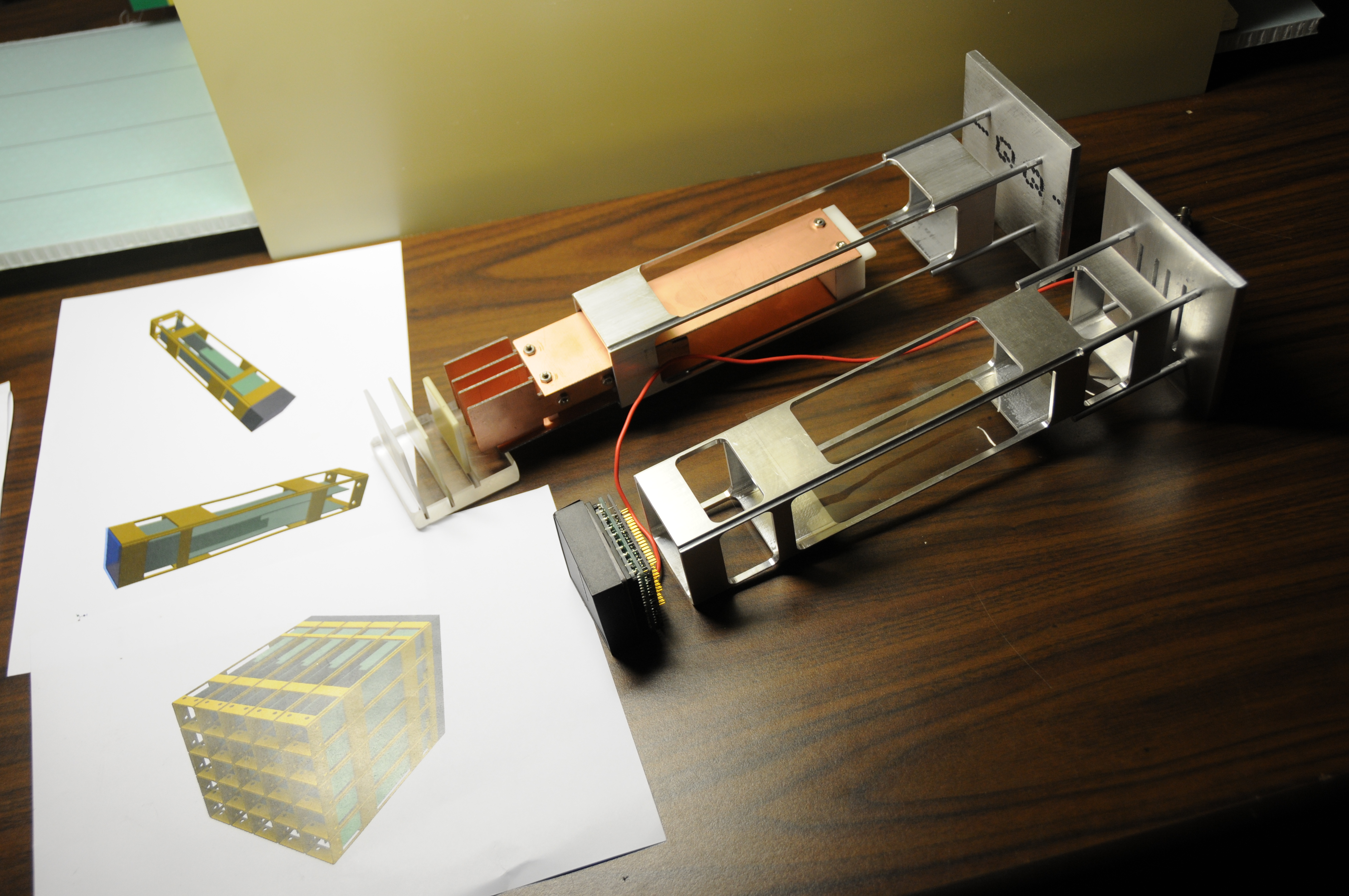
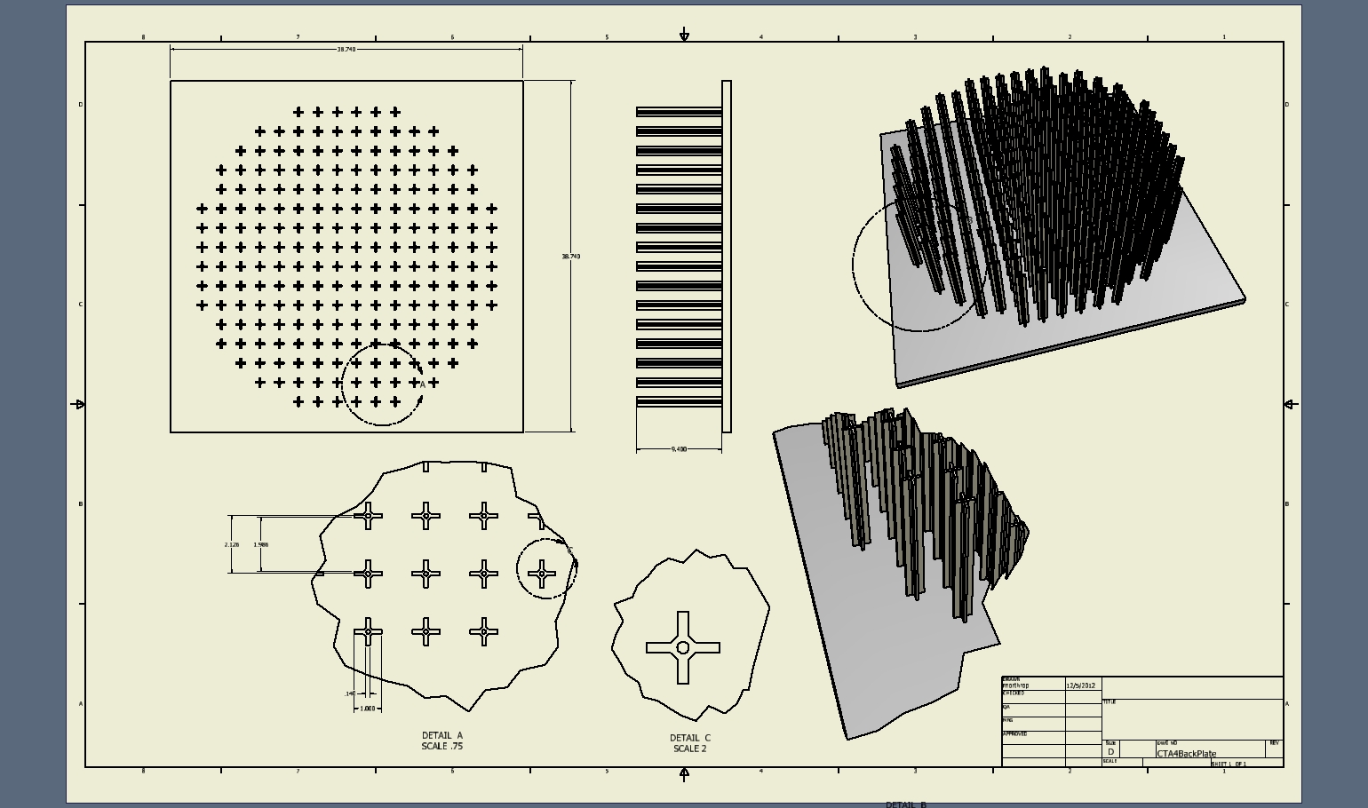
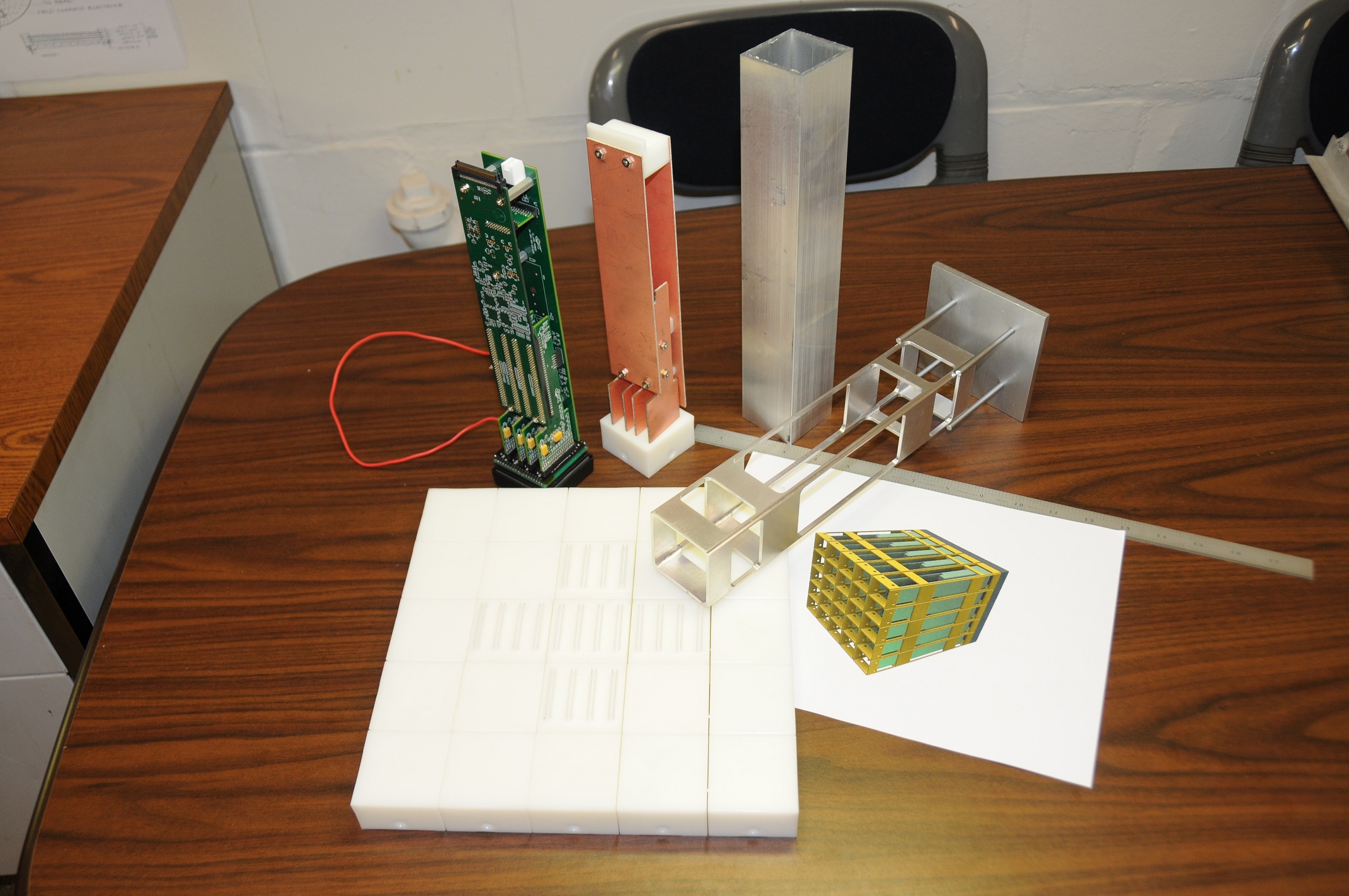 1 From left to right: 5x5 plastic mpmt mockup, SLAC electronics, UC electronics mockup, standard 2"x2" alum. extrusions, first UC machined cage, drawings of 5x5 detector array |
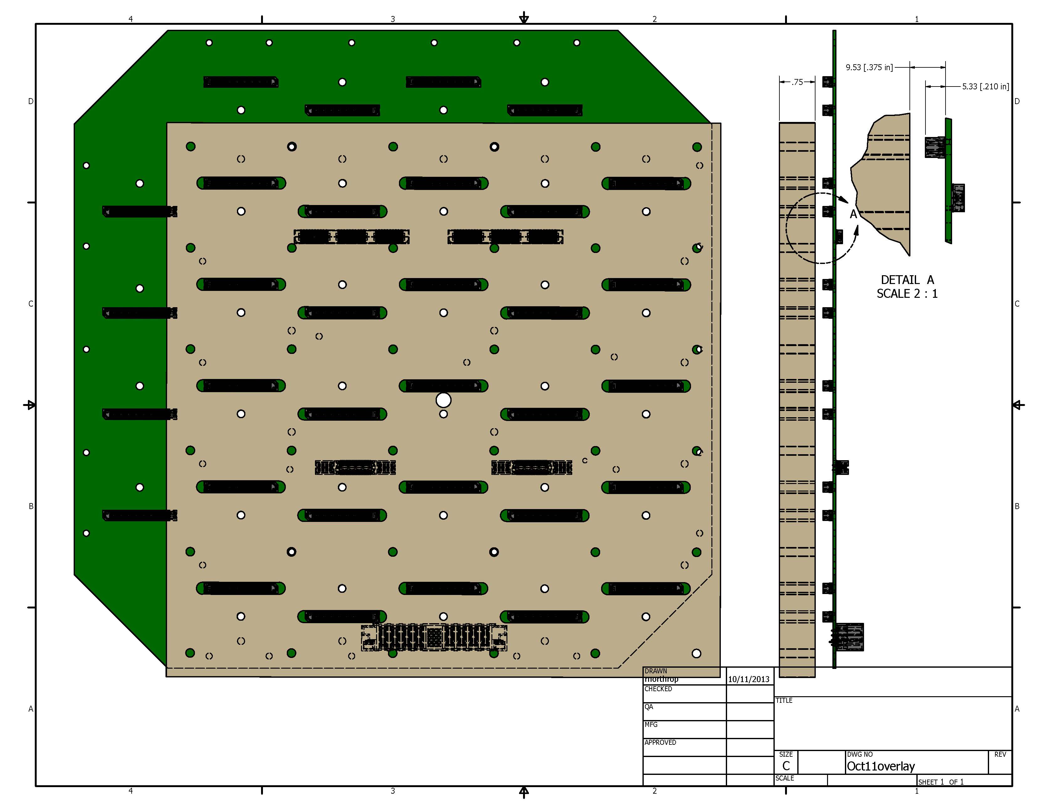
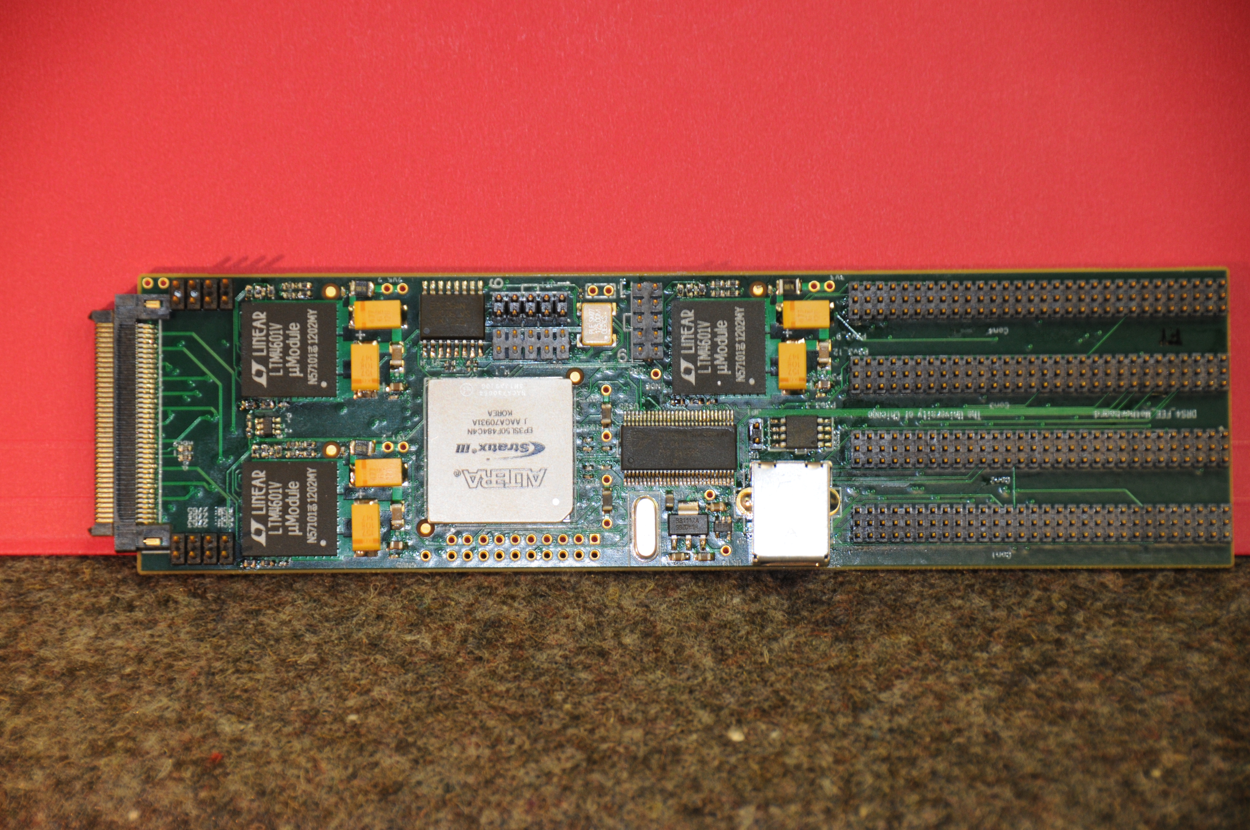 2 UC-EDG F.E.E. Motherboard |
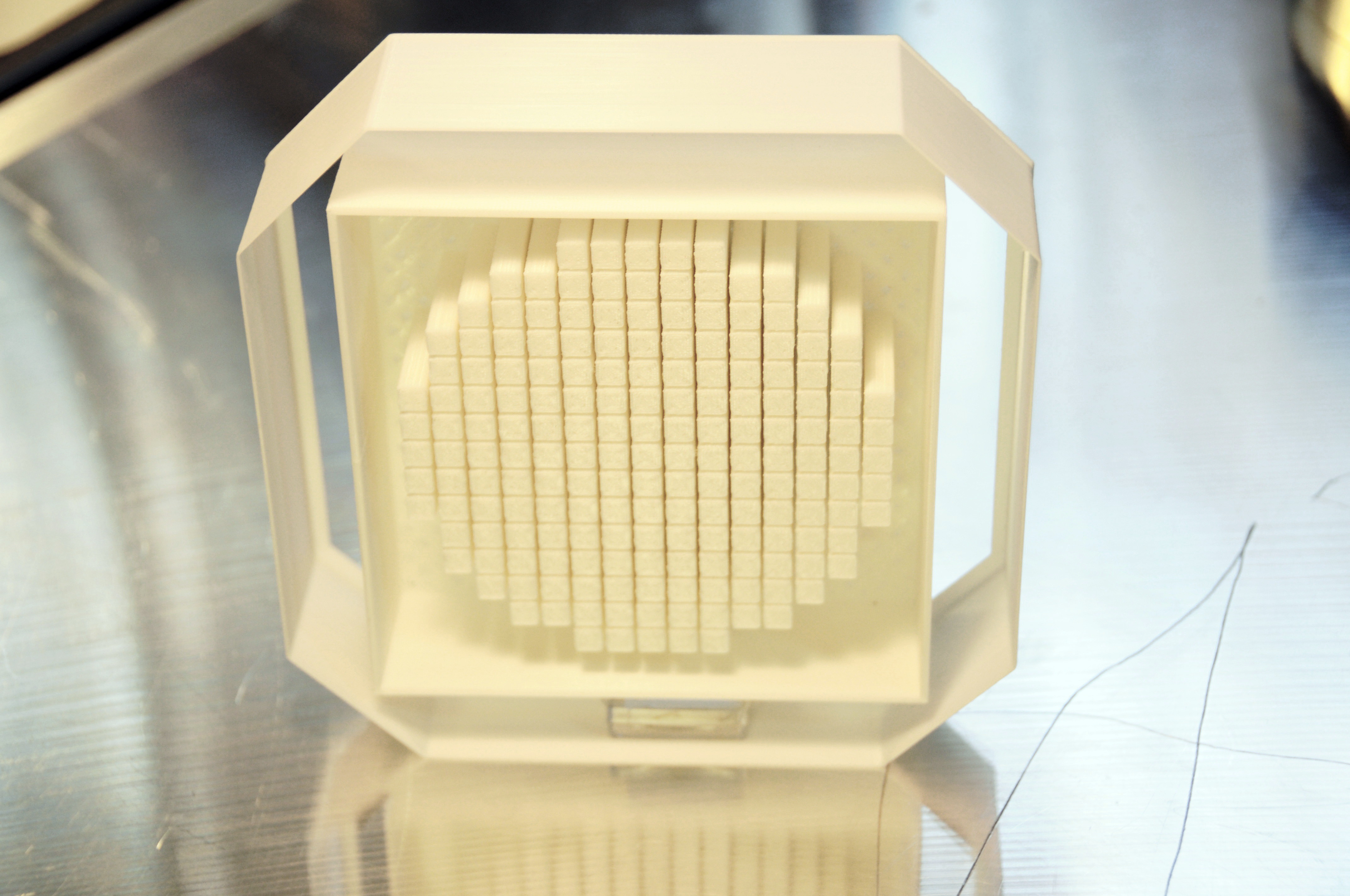
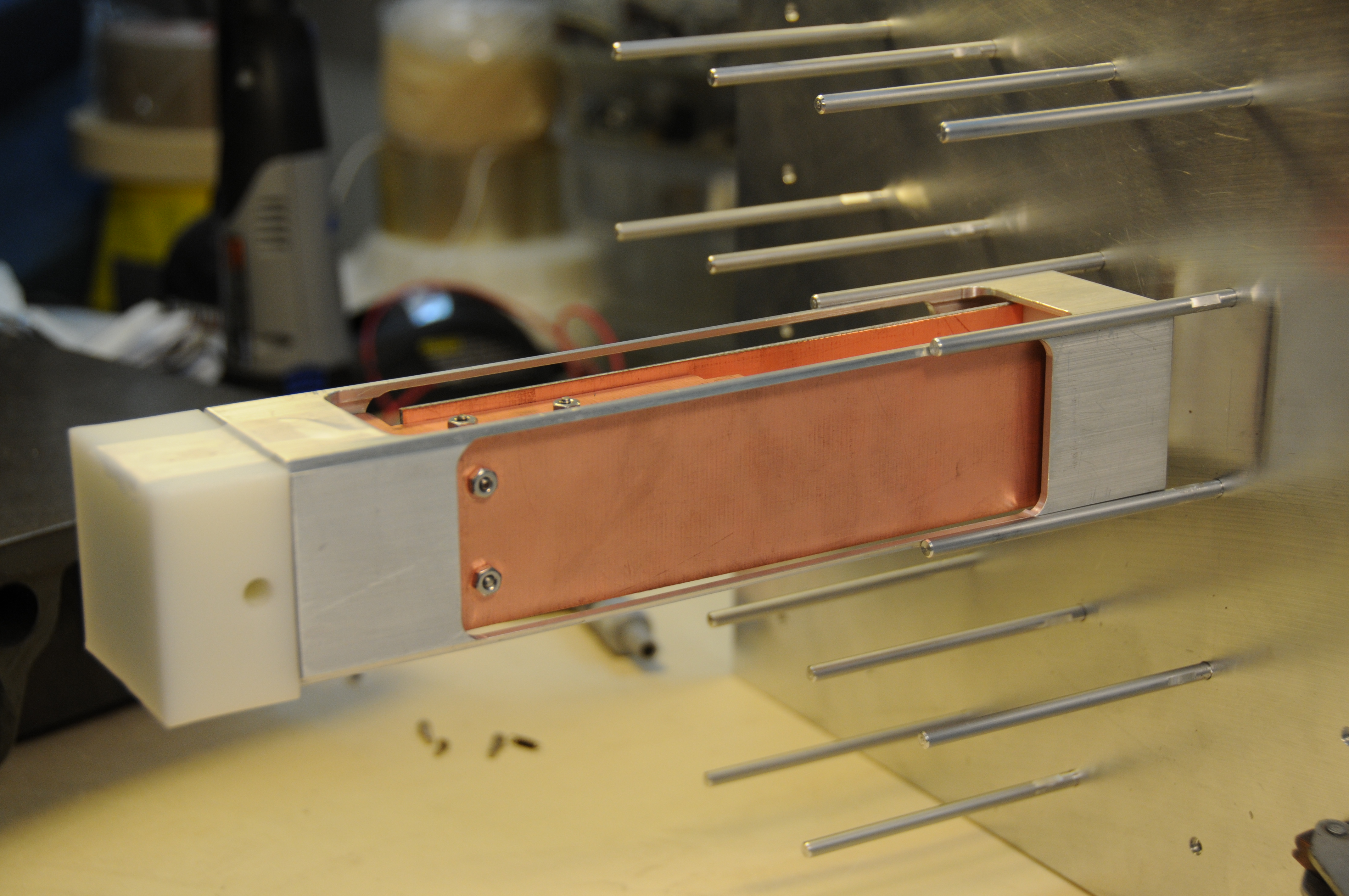 3 Second UC machined cage with electronics mockup with white mpmt mounted on support rods |
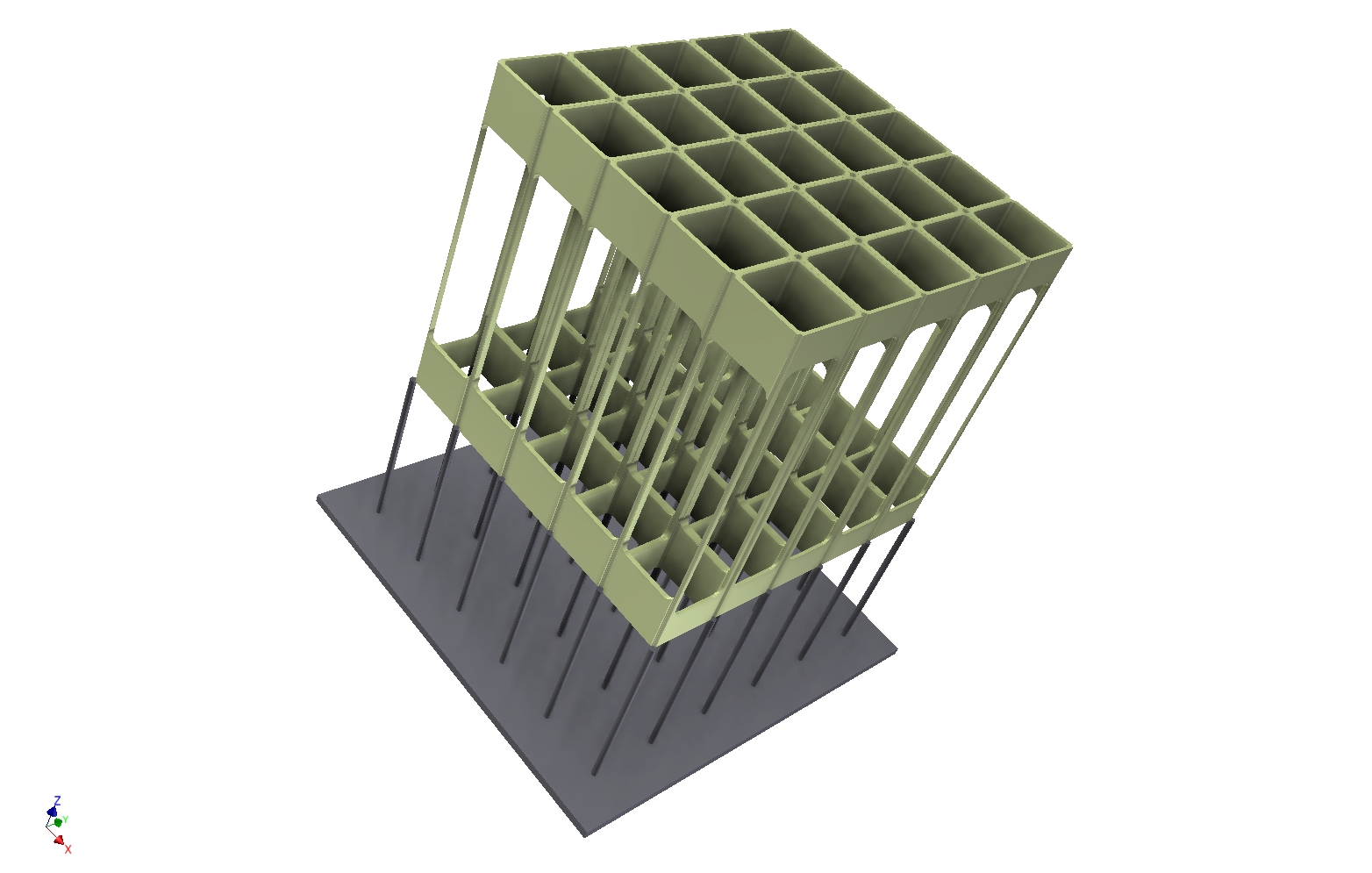 4 Drawing of 5x5 cage array sliding on support rods |
 5 Comparison of SiPM (top) with electronics and mpmt (bottom) |
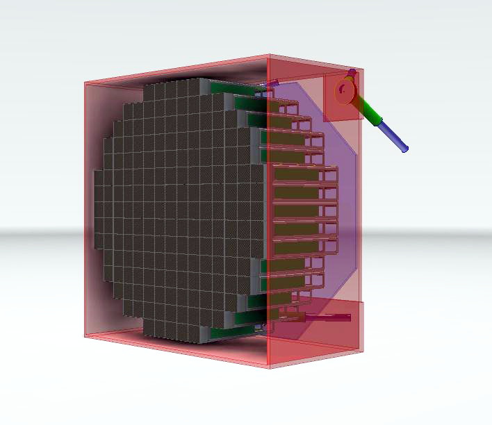 6 First concept of camera array mounted to inner camera box |
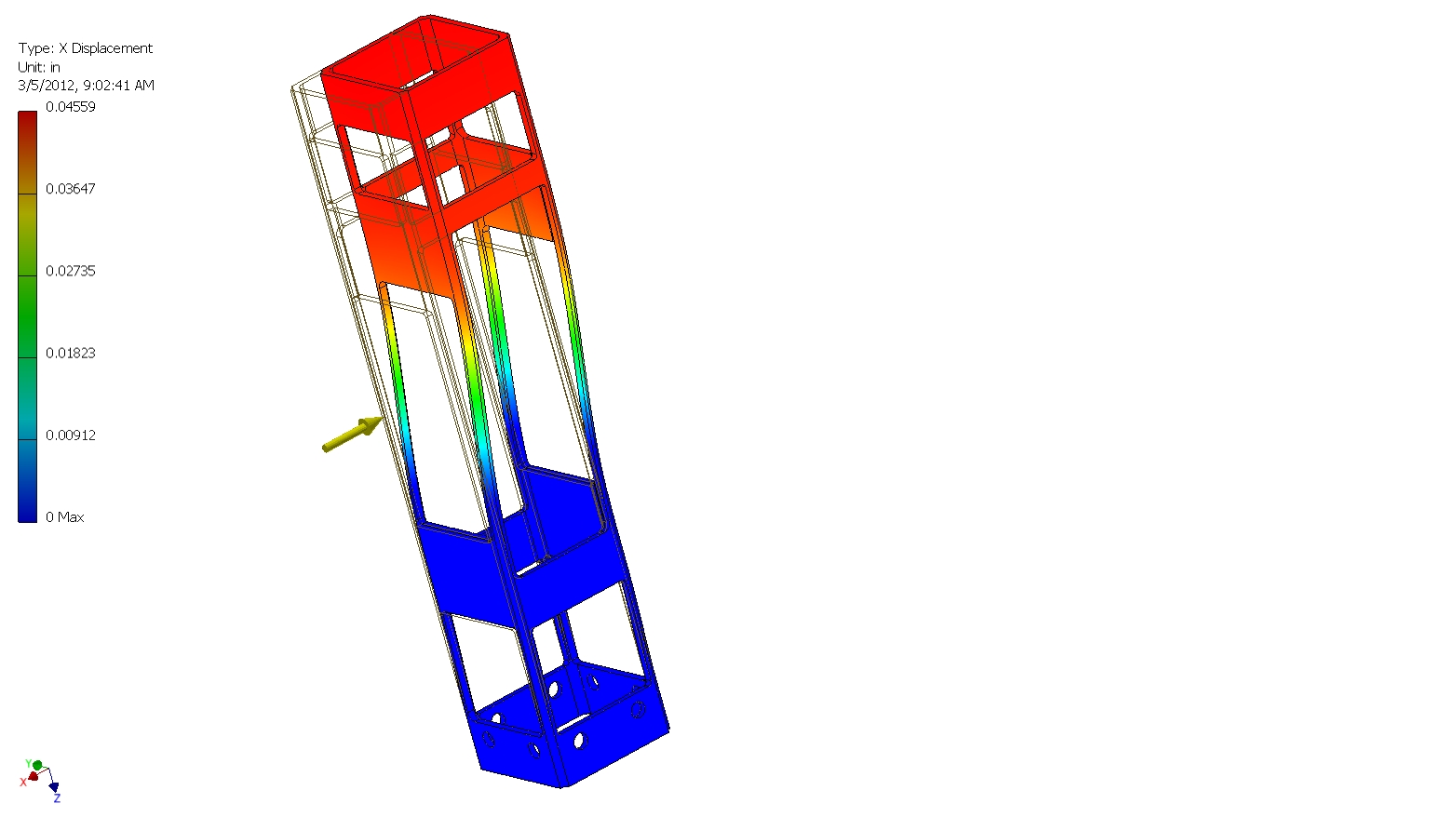 7 Alum. Cage deflection under 10 lb. UDL side load |
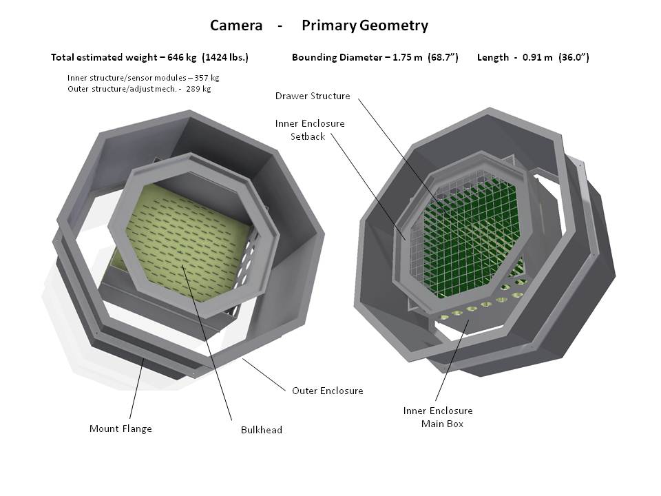
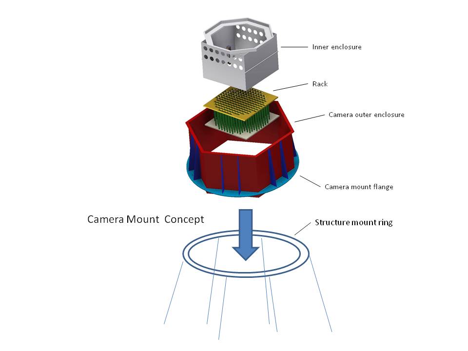
 8 Early camera concept showing inner & outer enclosures; also shows Mounting flange to Camera structure |
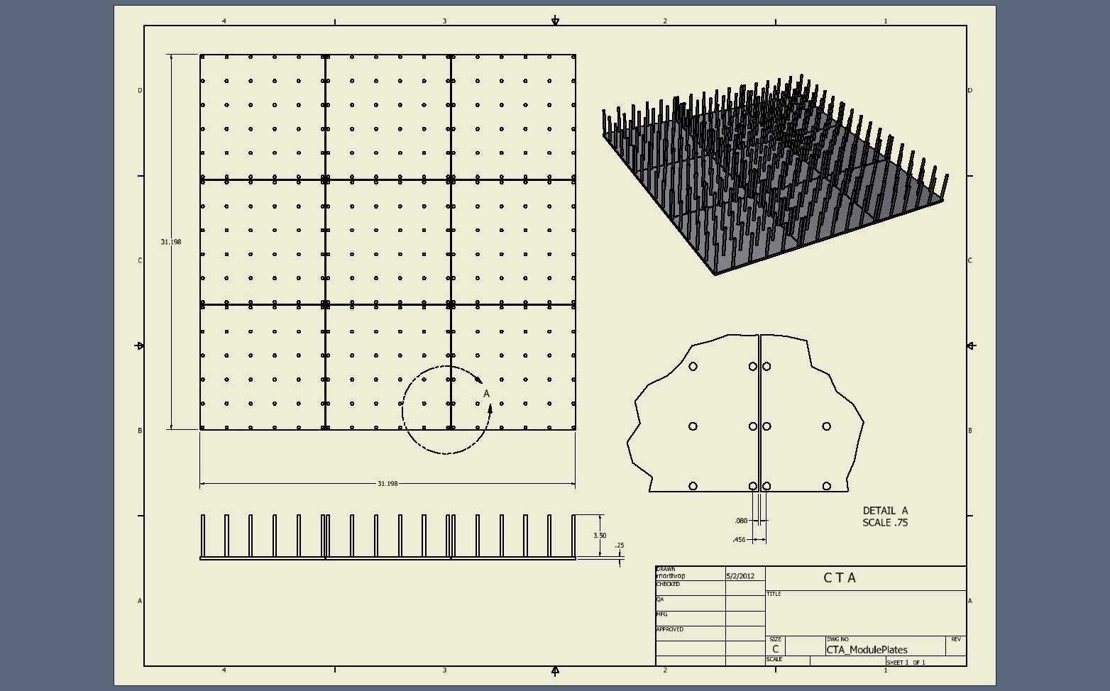 9 Camera sub-module plate square arrangement |
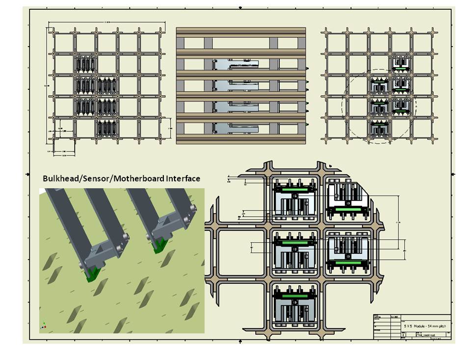
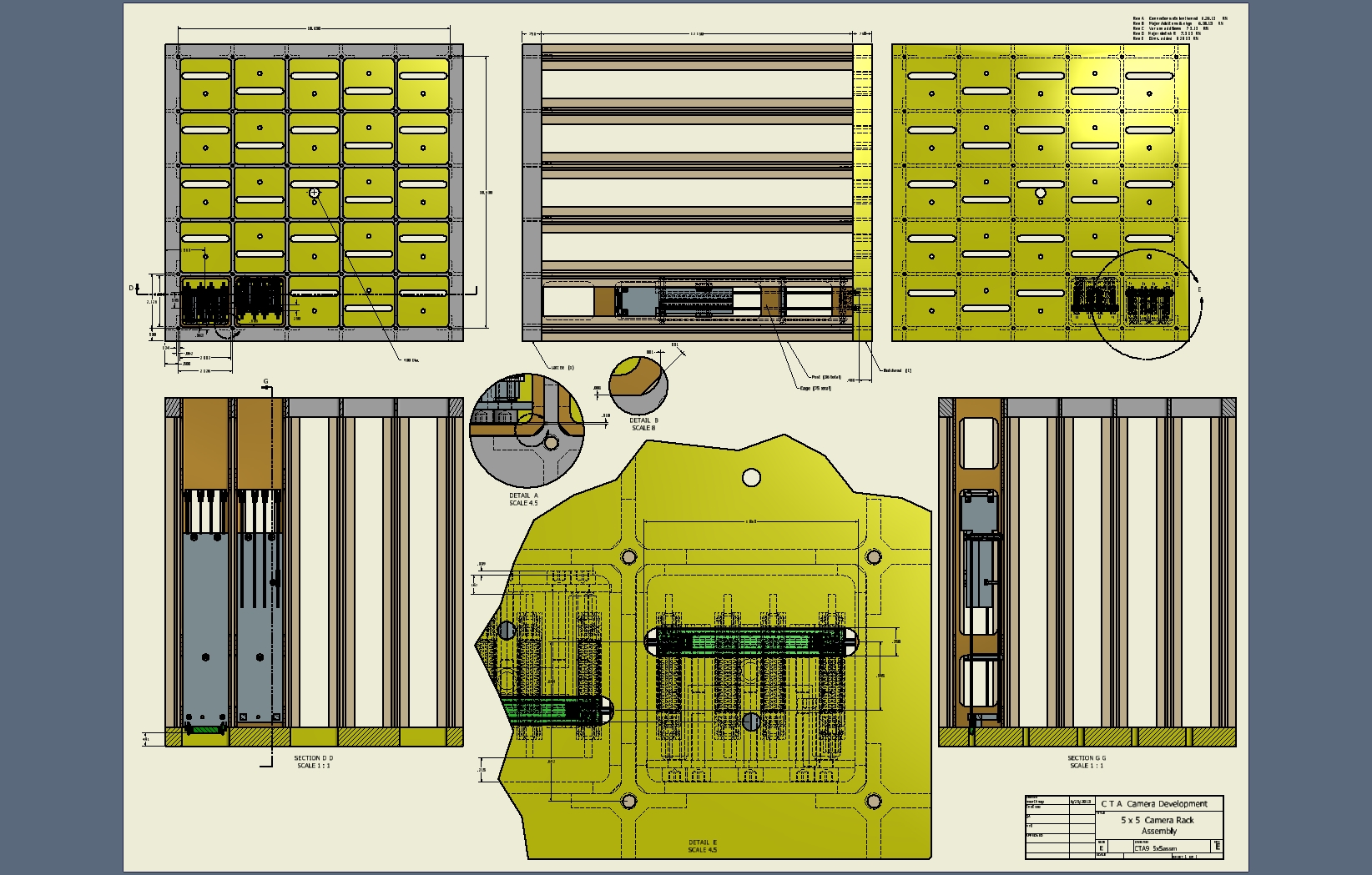
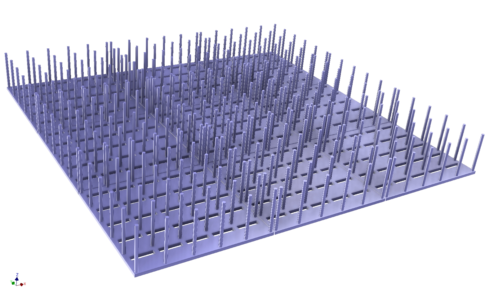 10 5 x 5 sensor module plate array showing connector access & support rods. |
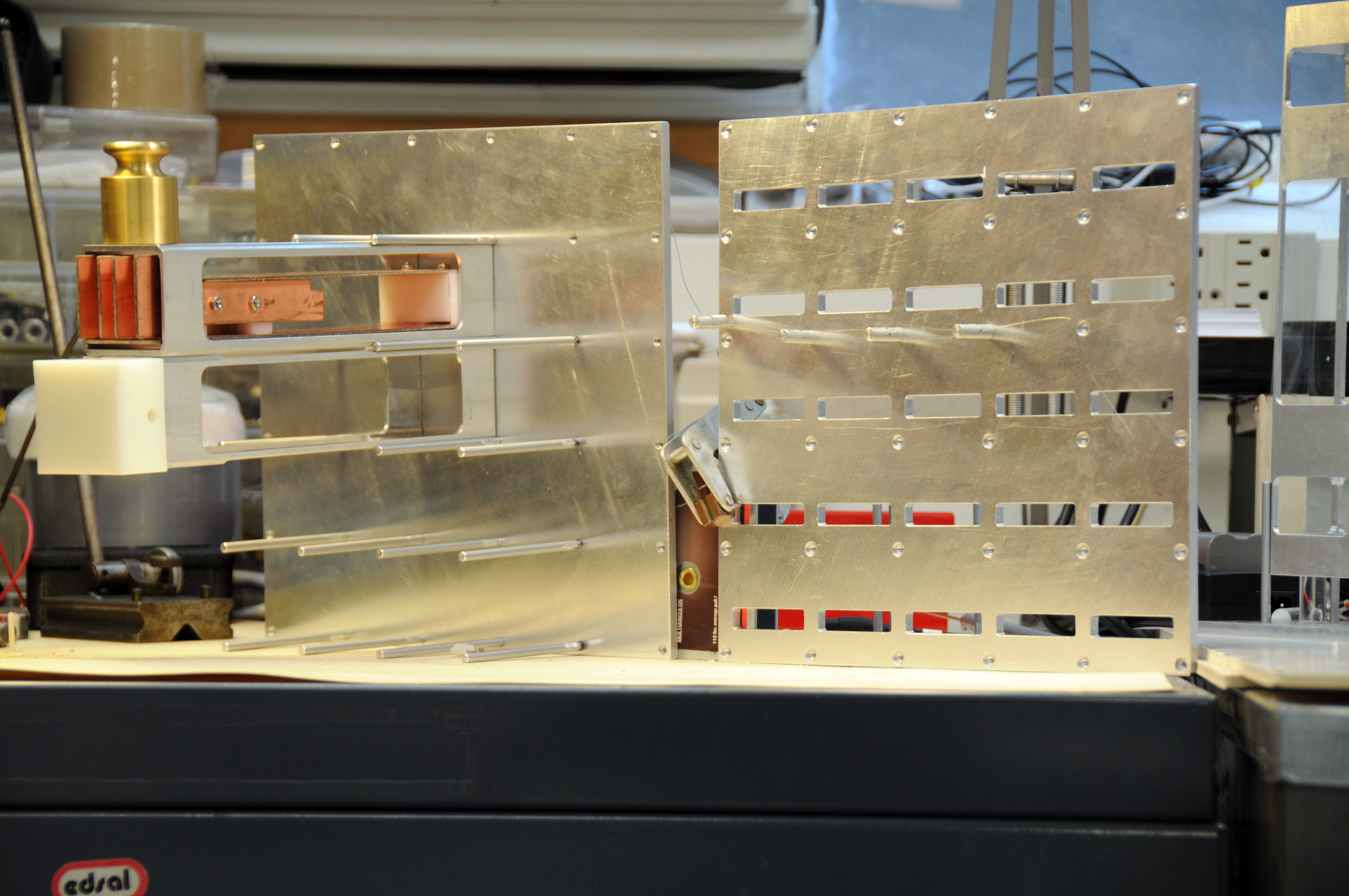 11 Load & fit test of module/rod support, also showing type 2 module under construction. |
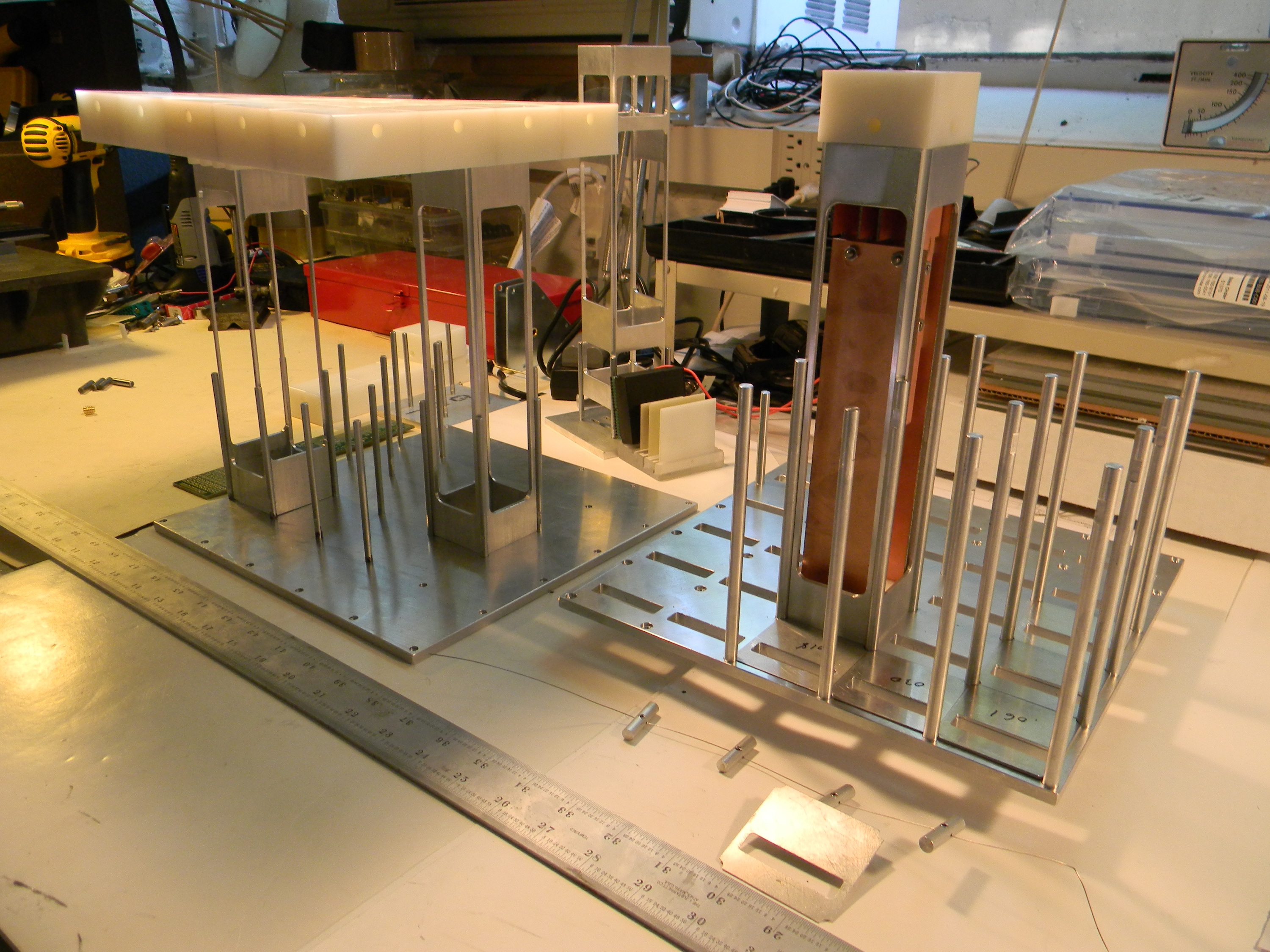 12 Type 2 module (on right) with several riser shims in assembly and foreground. |
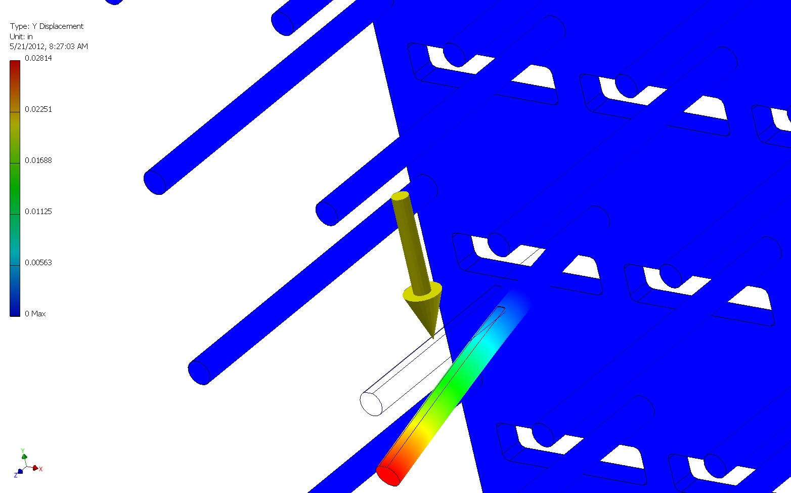 13 Pin deflection under 8 lb. load on 2.0” end length. |
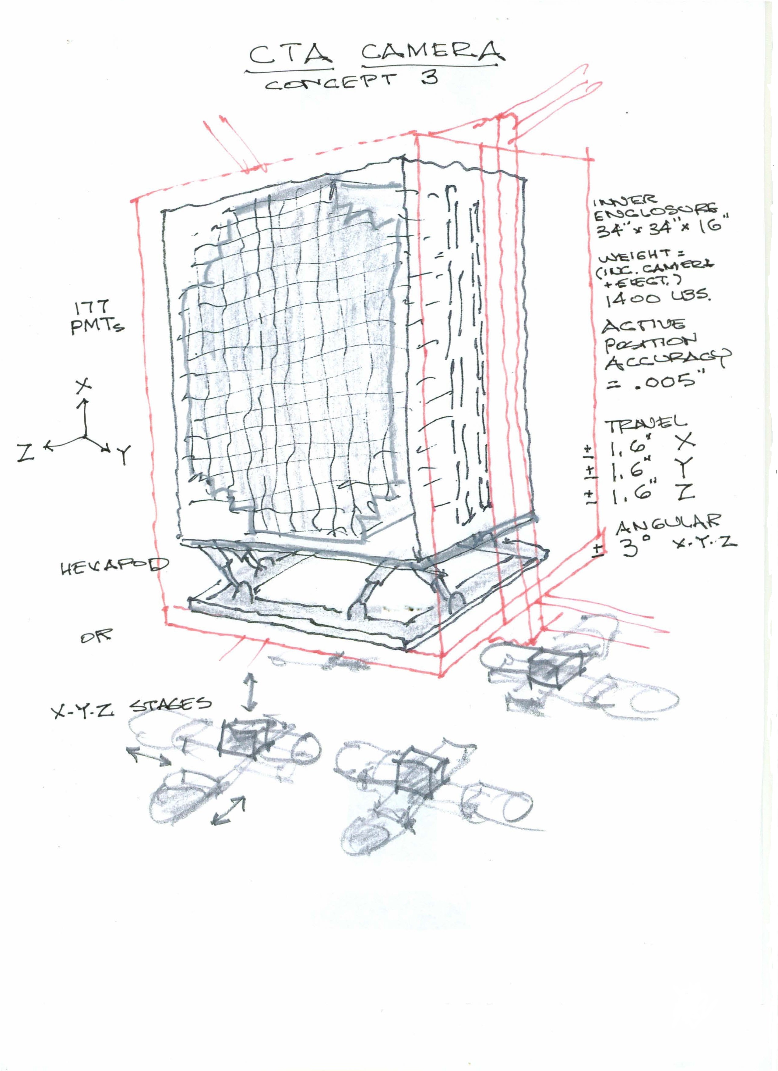 14 Concept sketch for side hexapod mount. |
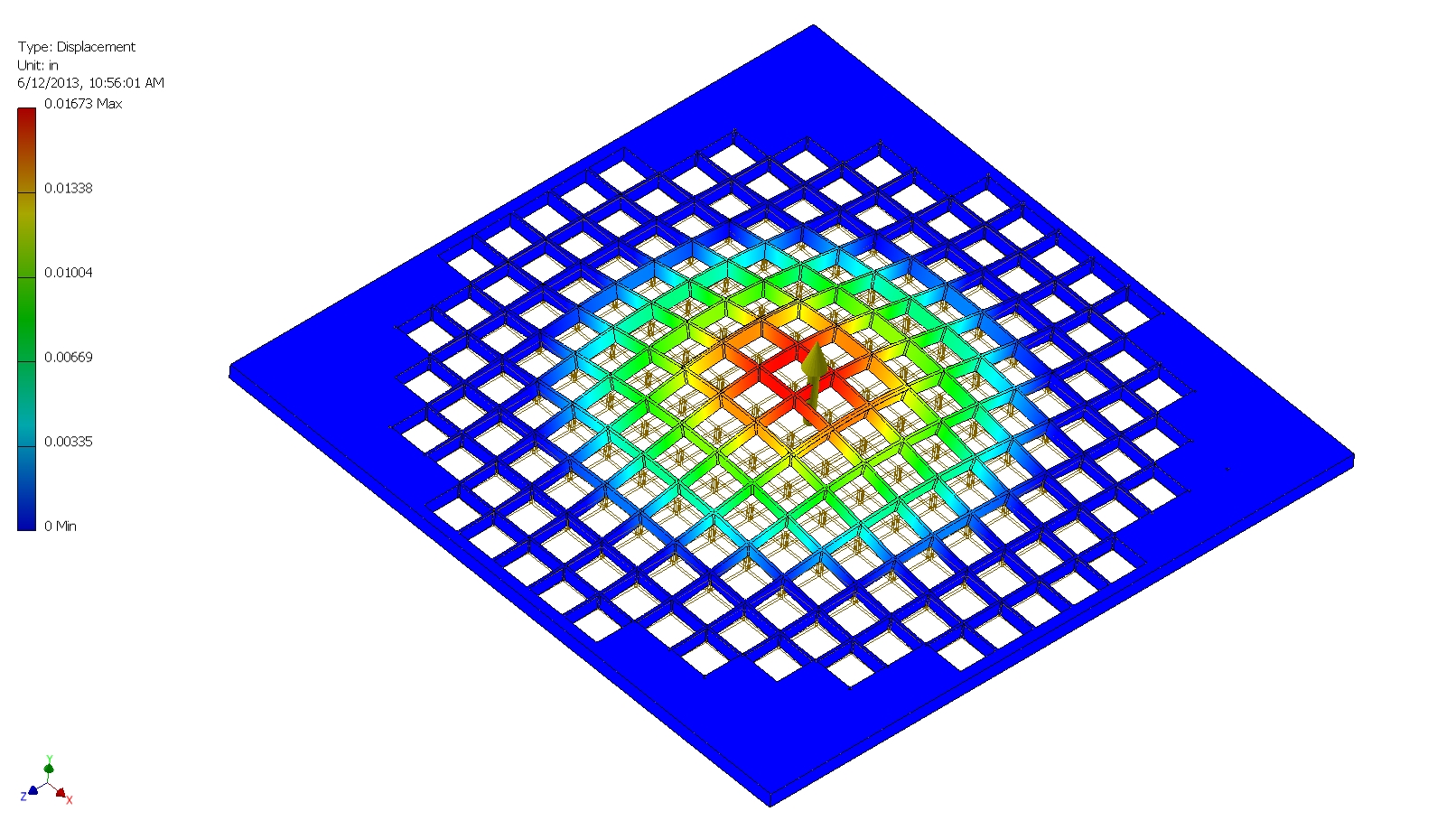
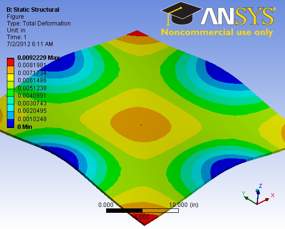 15 33” x 33” x 3/8” camera front aluminum support plate deflections under 200 lbs. UDL with 4 mid-span edge supports. |
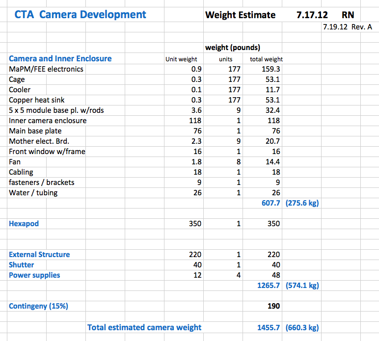 16 Camera weight estimate |
 17 |
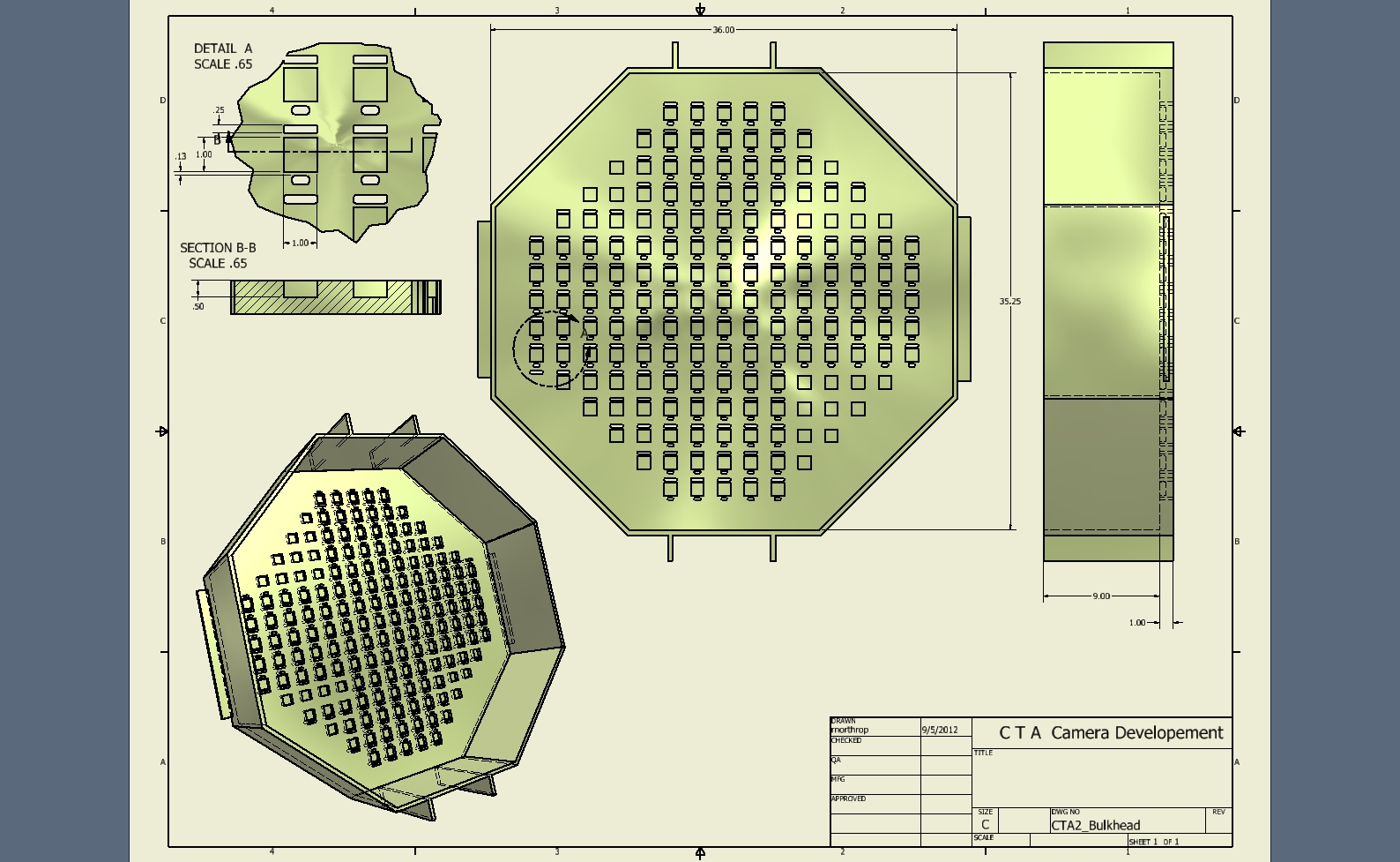
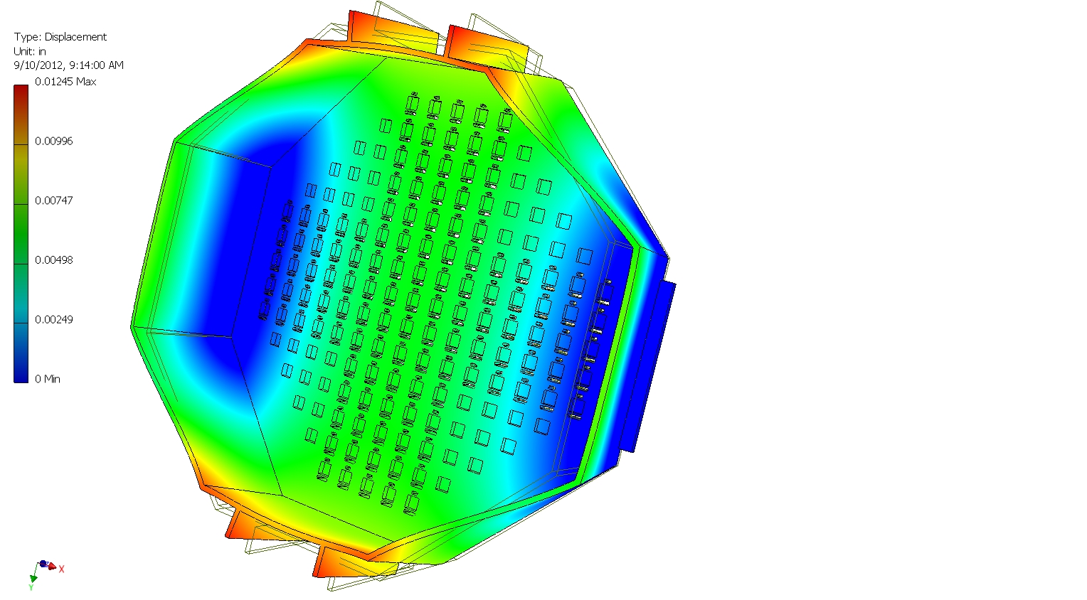 18 Bulkhead plate deflection under 600 lb. UDL with 2 opposite edge supports. |
 19 |
 20 |
 21 Camera rear view showing inner enclosure, electronics, and outer shell - Conceptual Design |
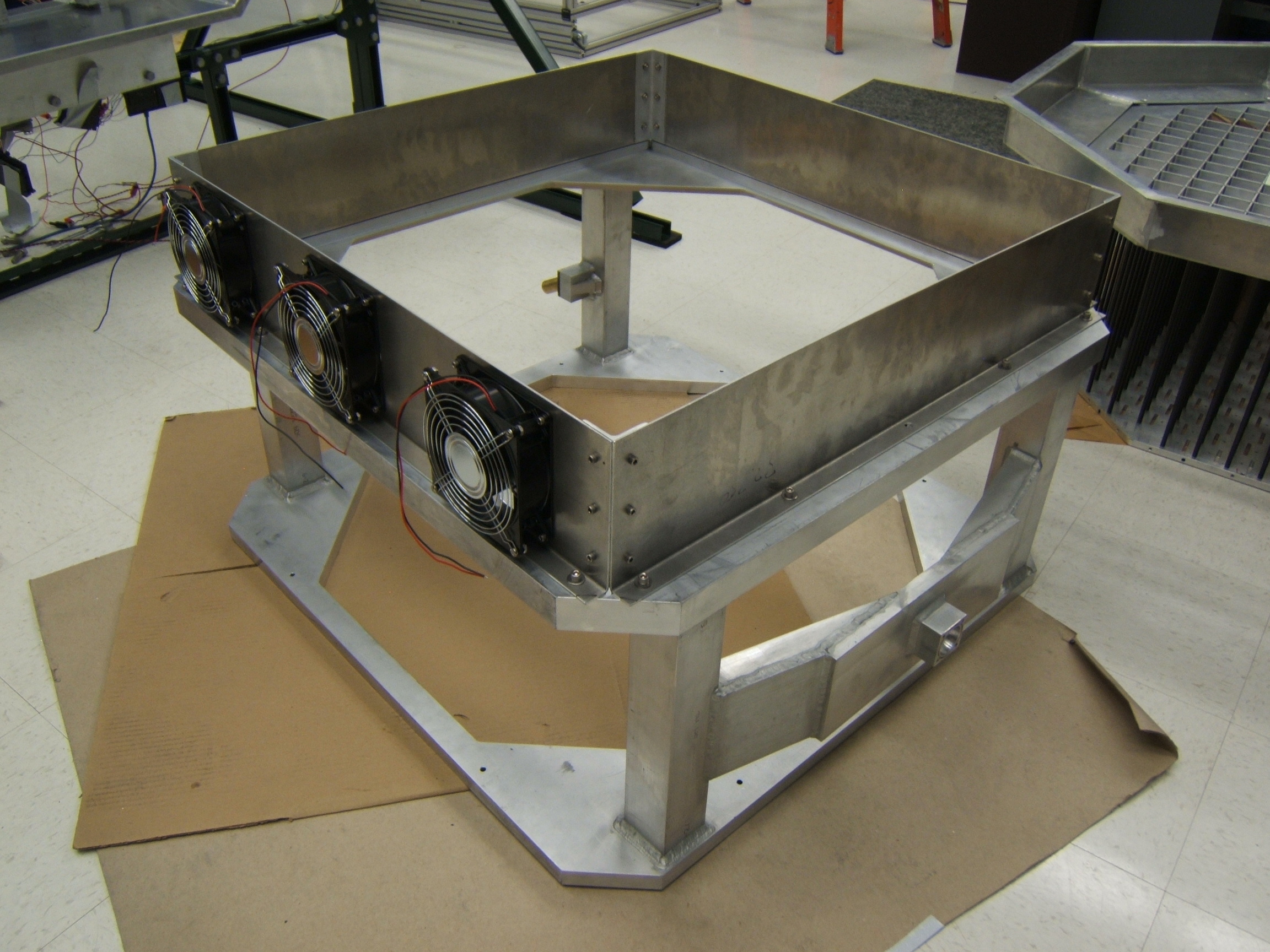
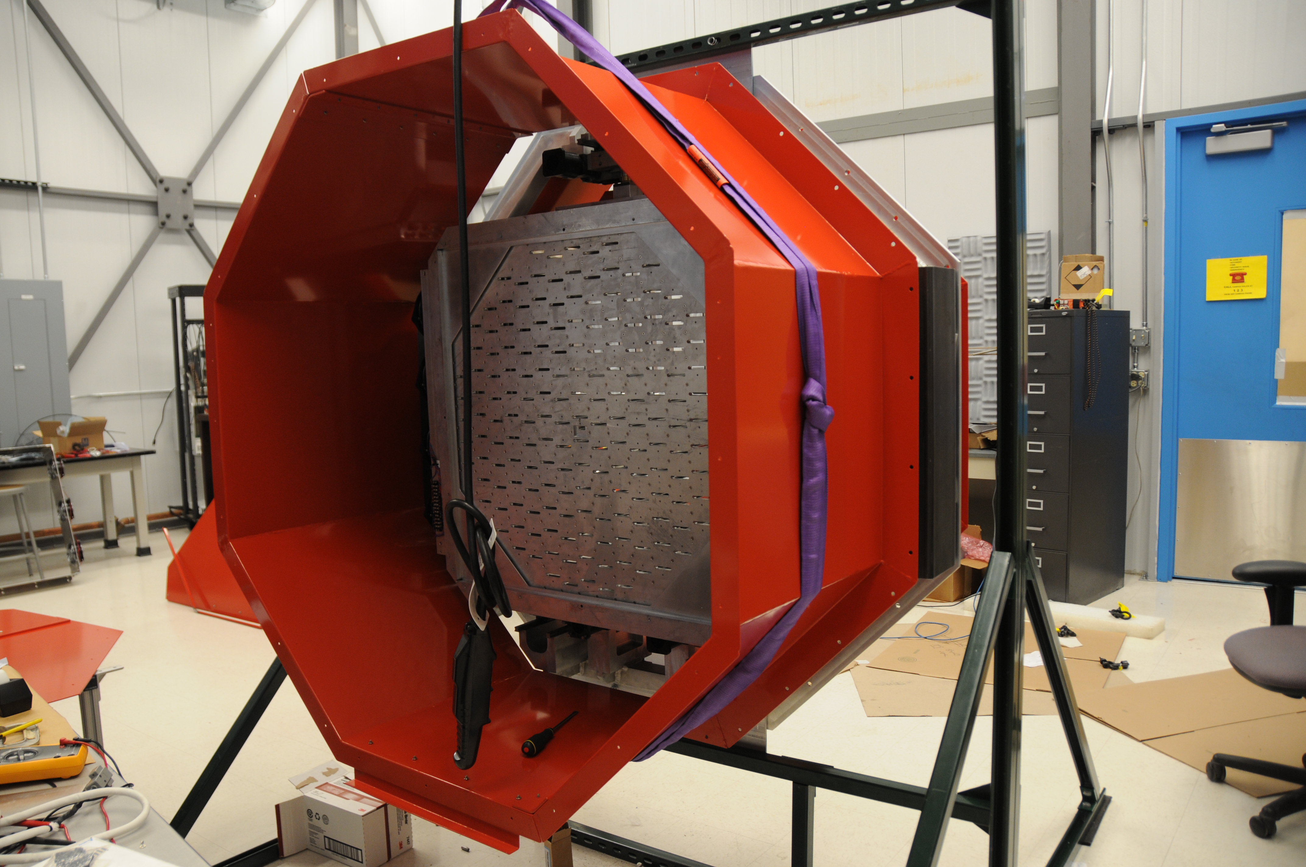
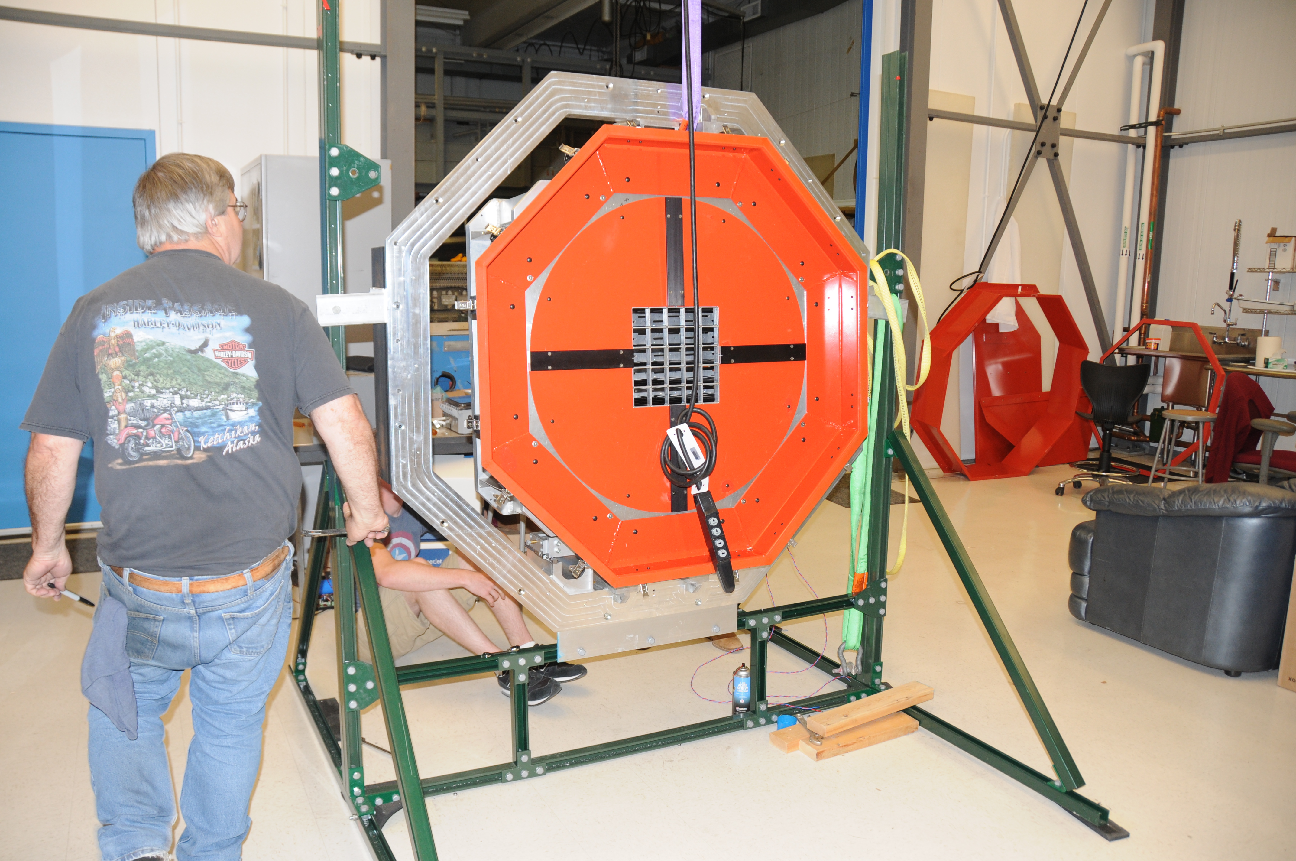
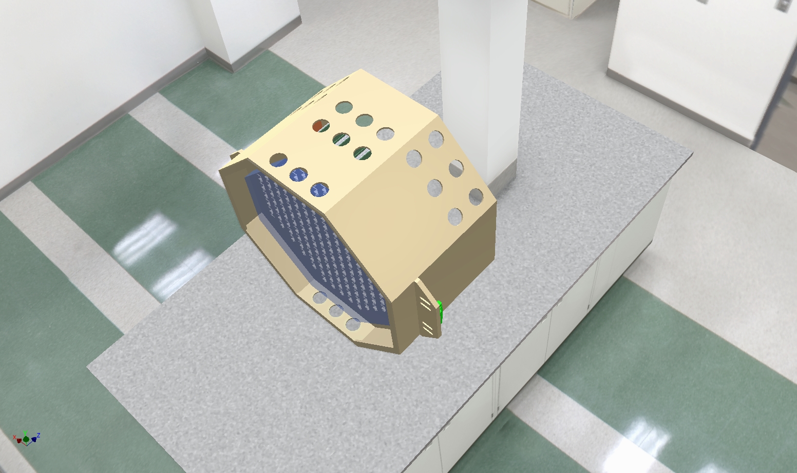 22 Camera ready for testing |
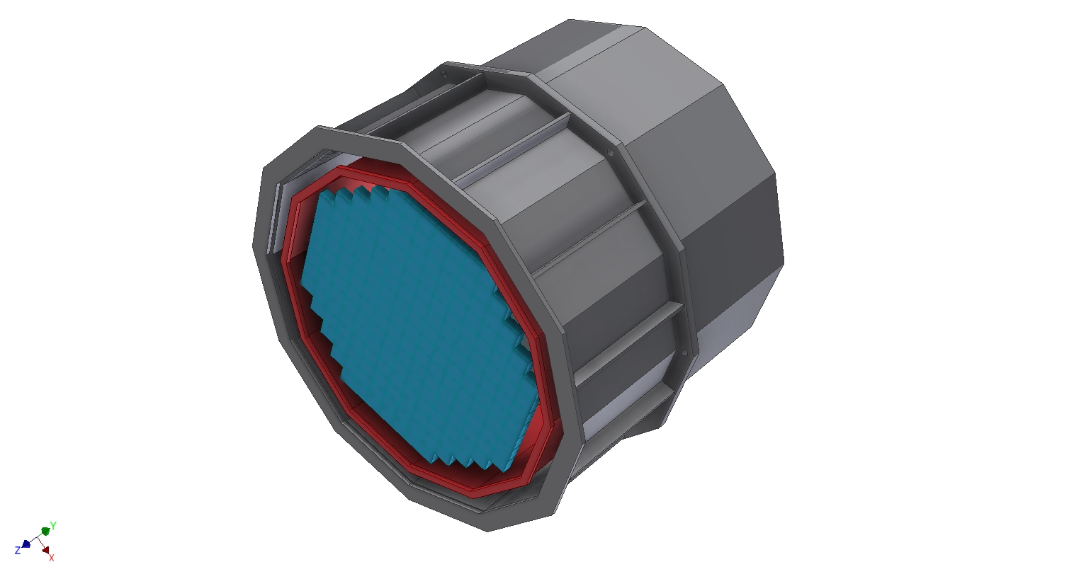
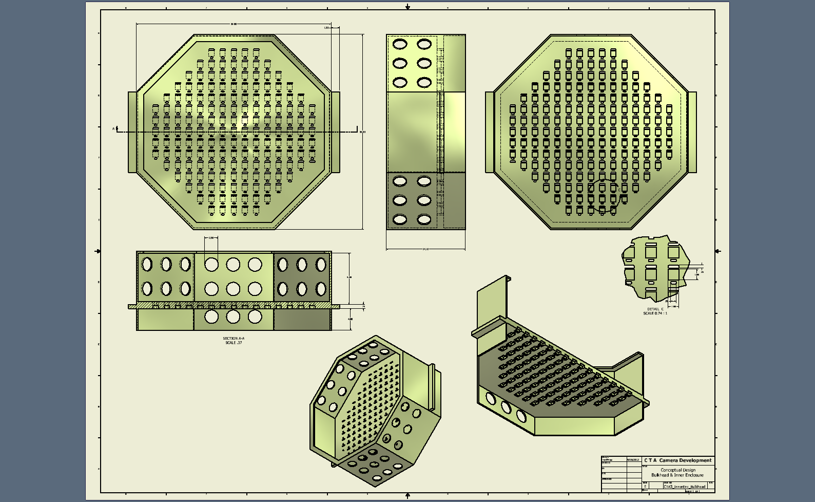
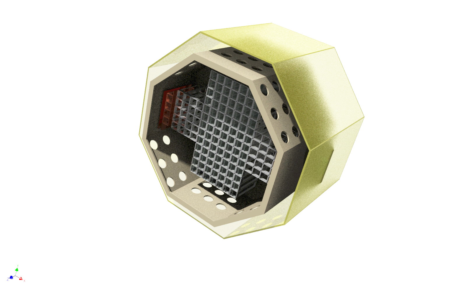
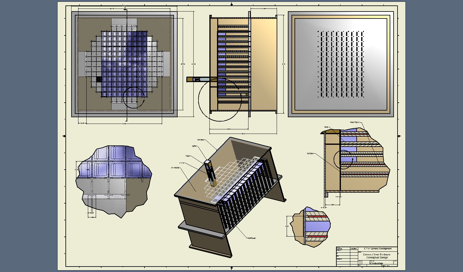
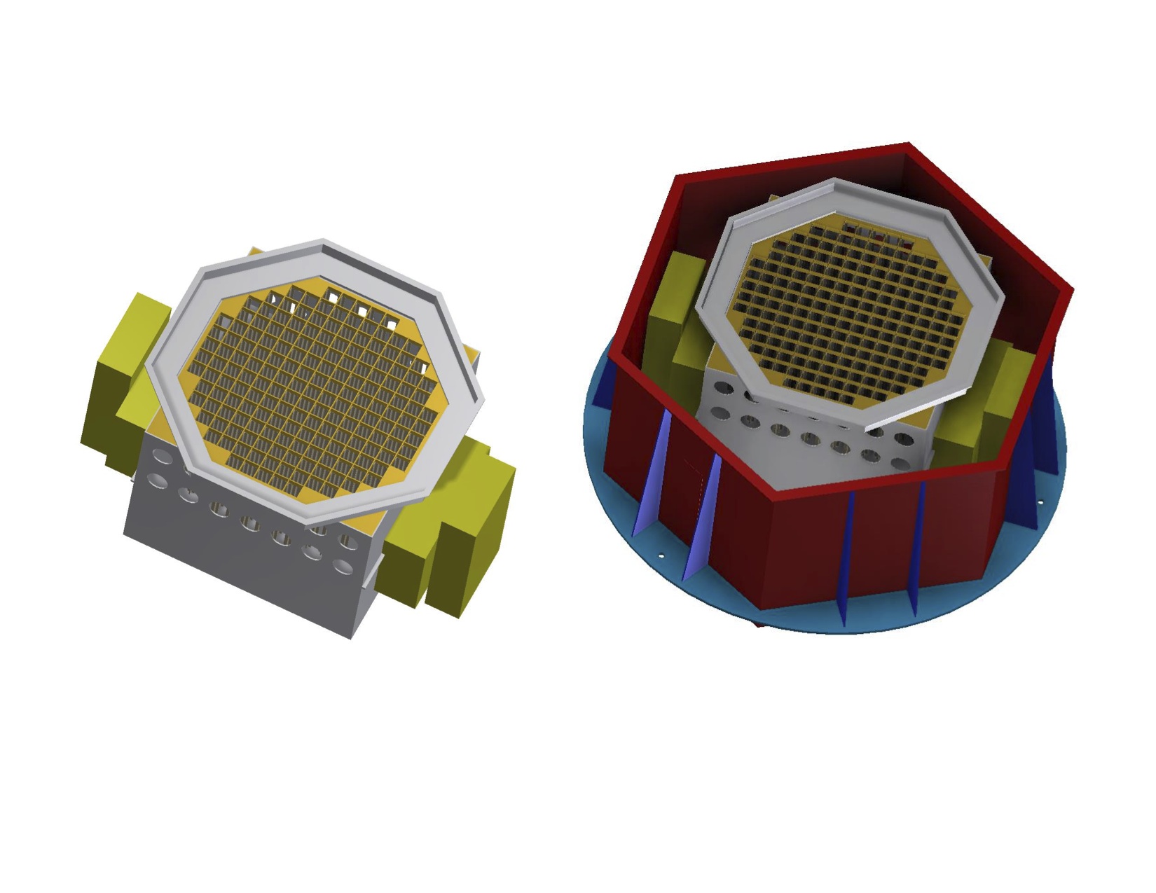
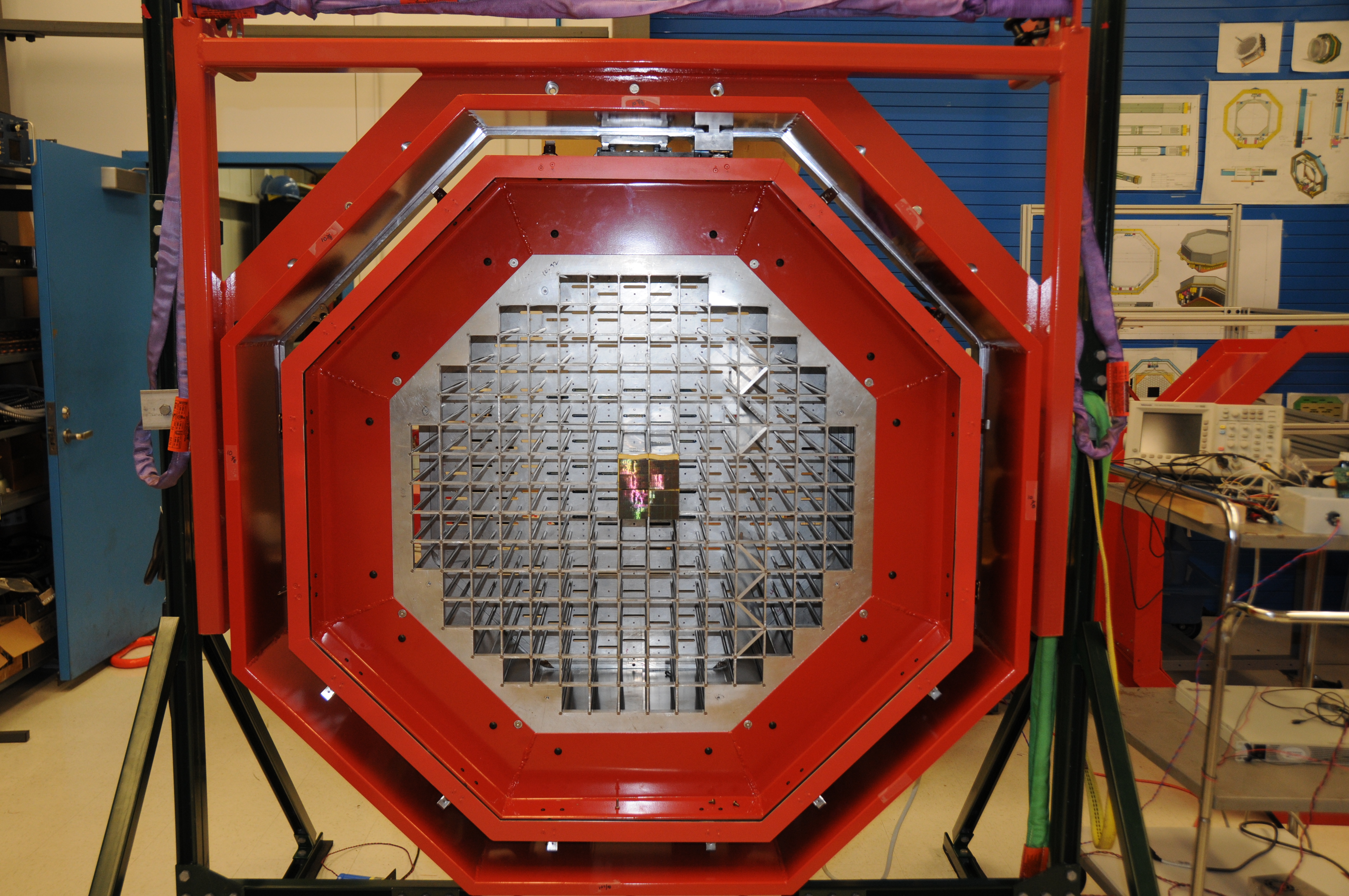
 23 Inner Enclosure with Camera Arrangment |
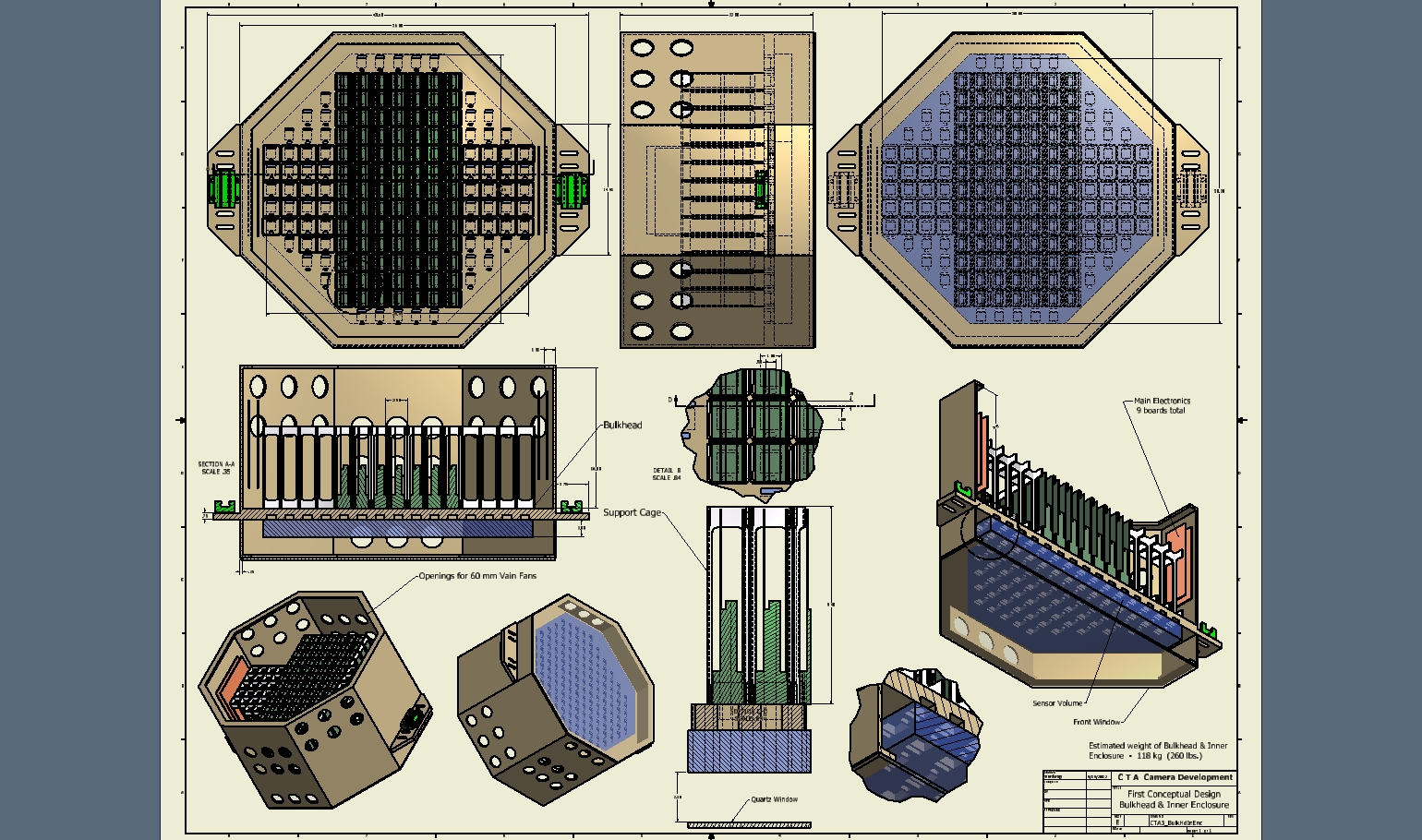
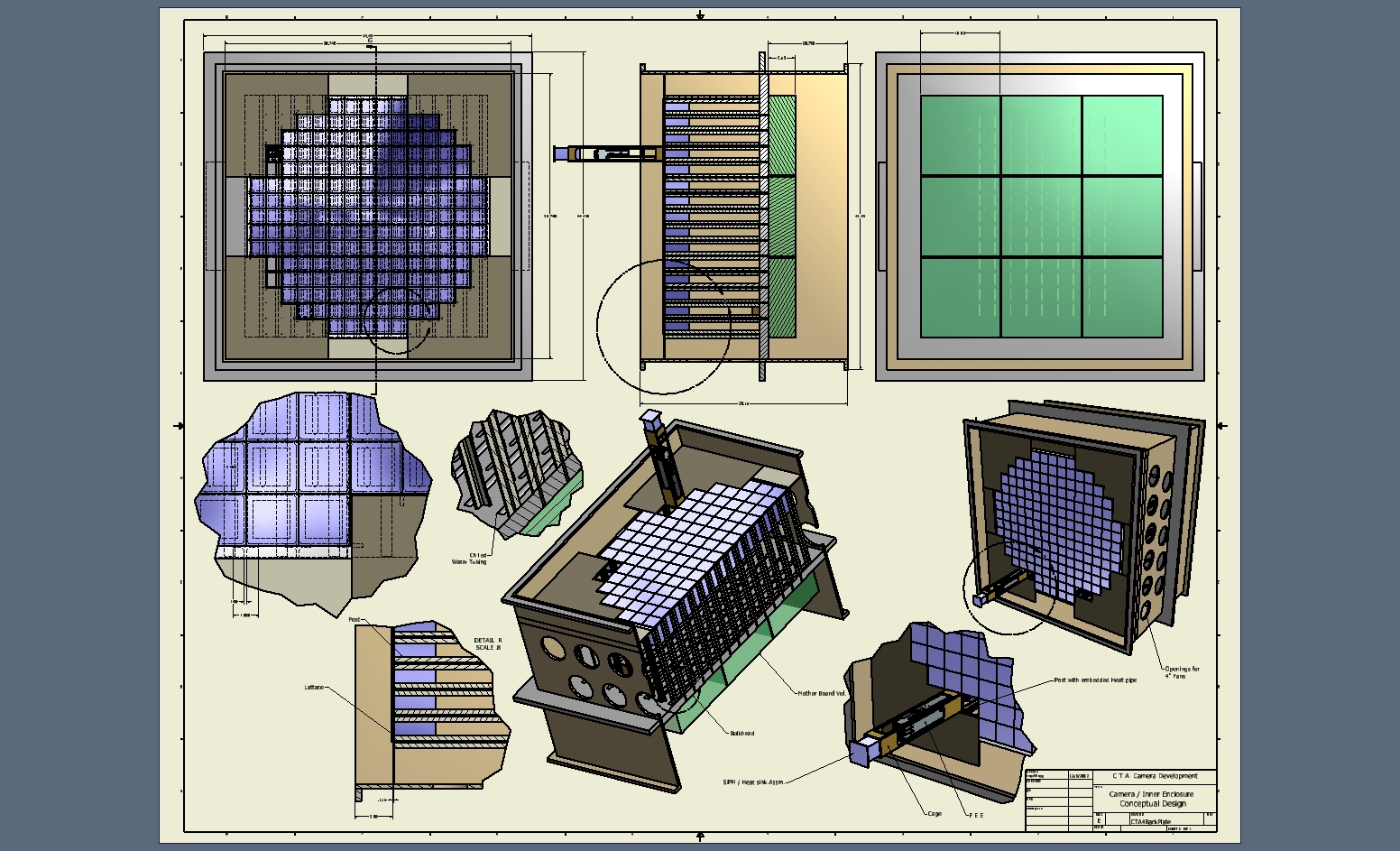
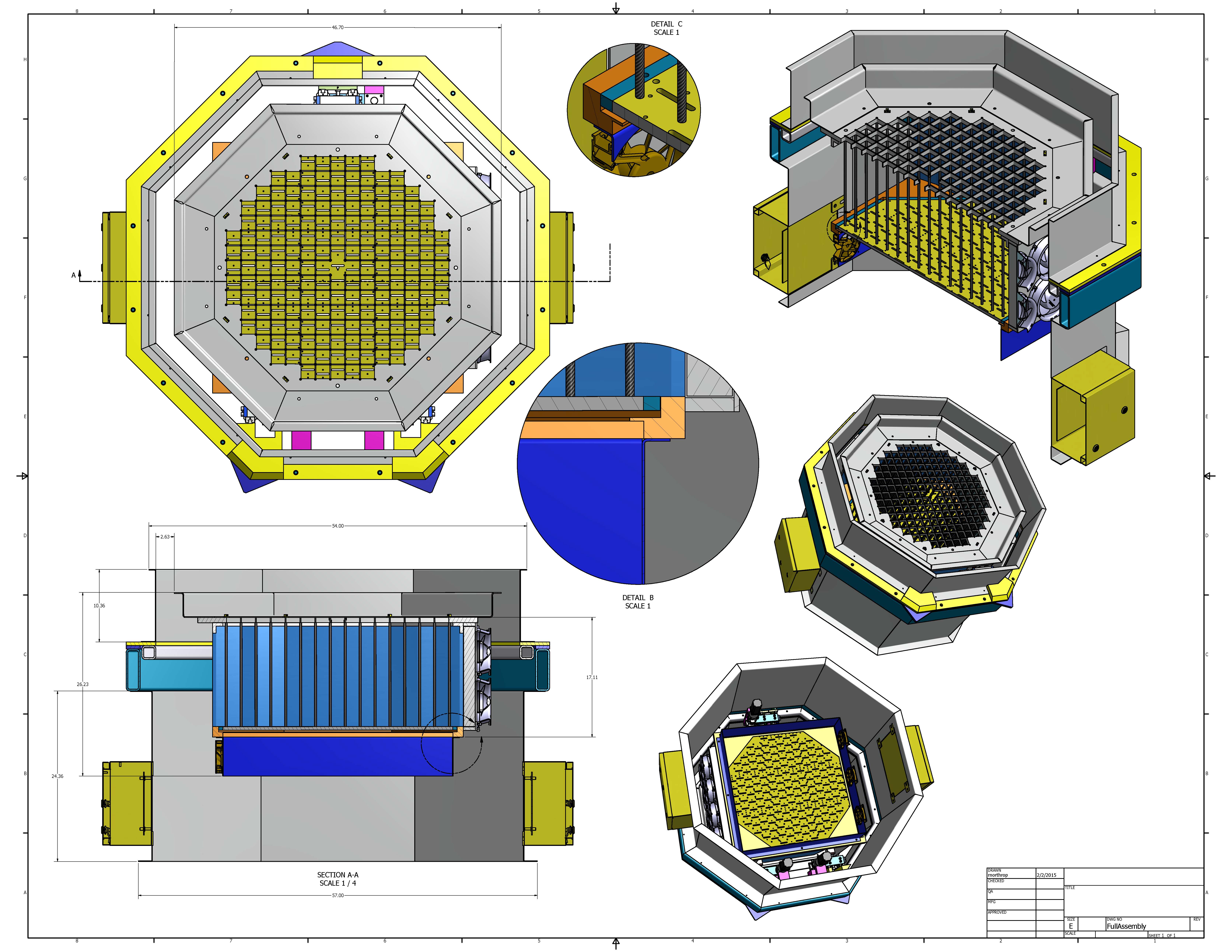
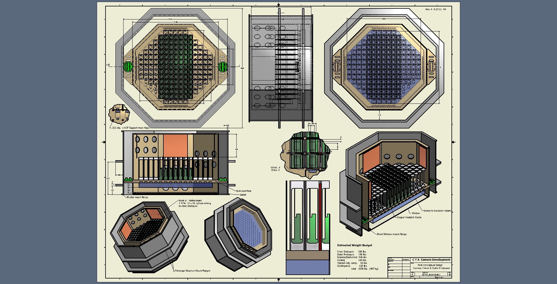 24 Conceptual Design & weight estimates of Complete Camera Assembly for Review |
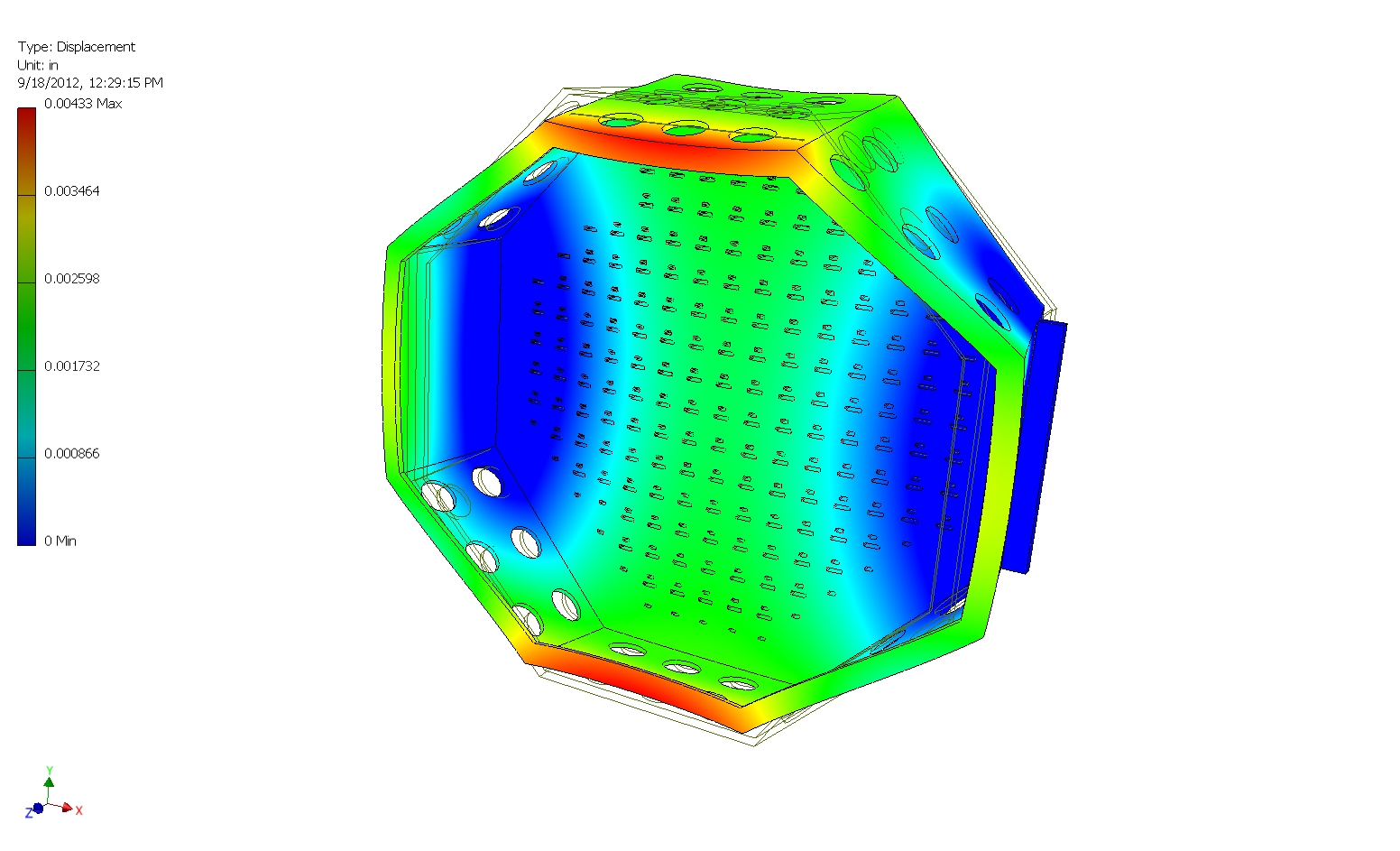
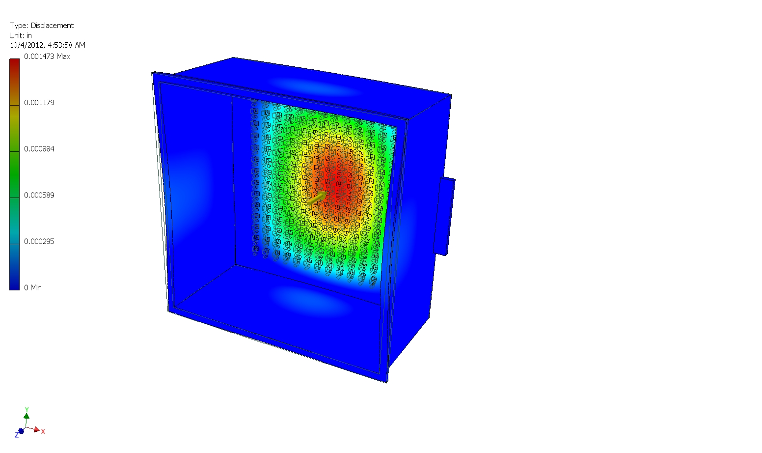 25 Bulkhead deflection for square enclosure design with same settings as image 18 |
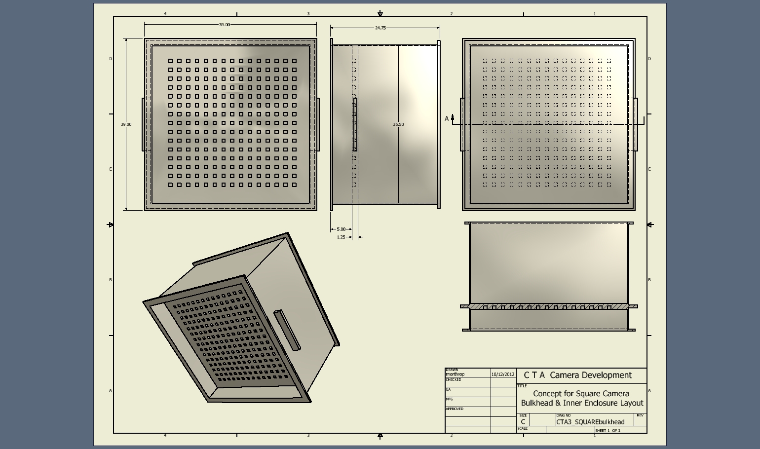 26 Square Camera Configuration – showing Bulkhead and Inner Enclosure |
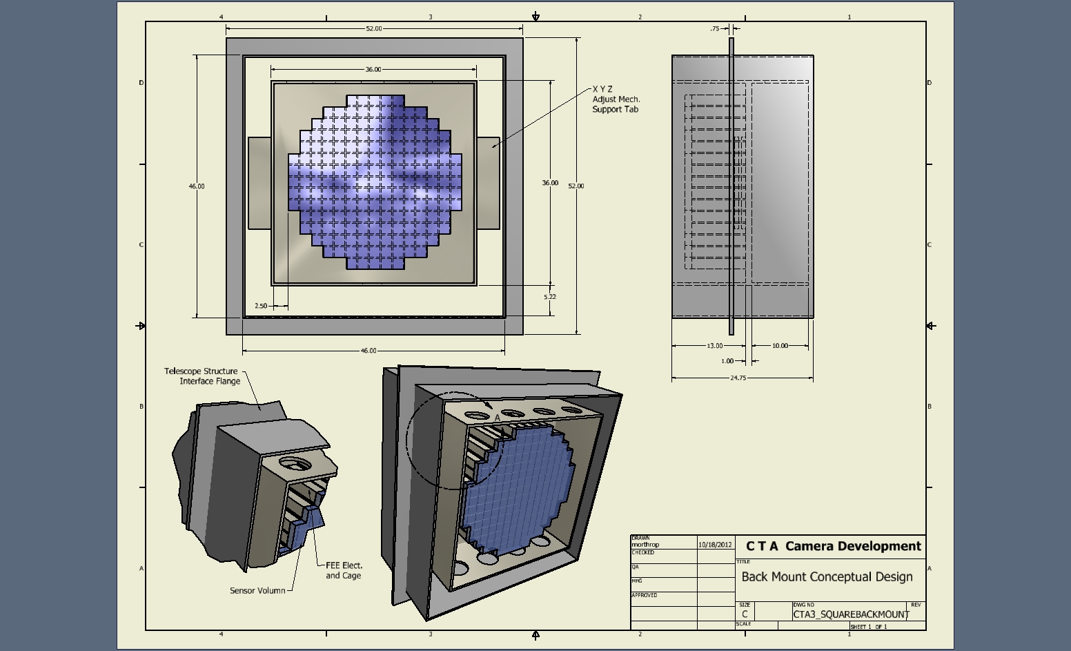
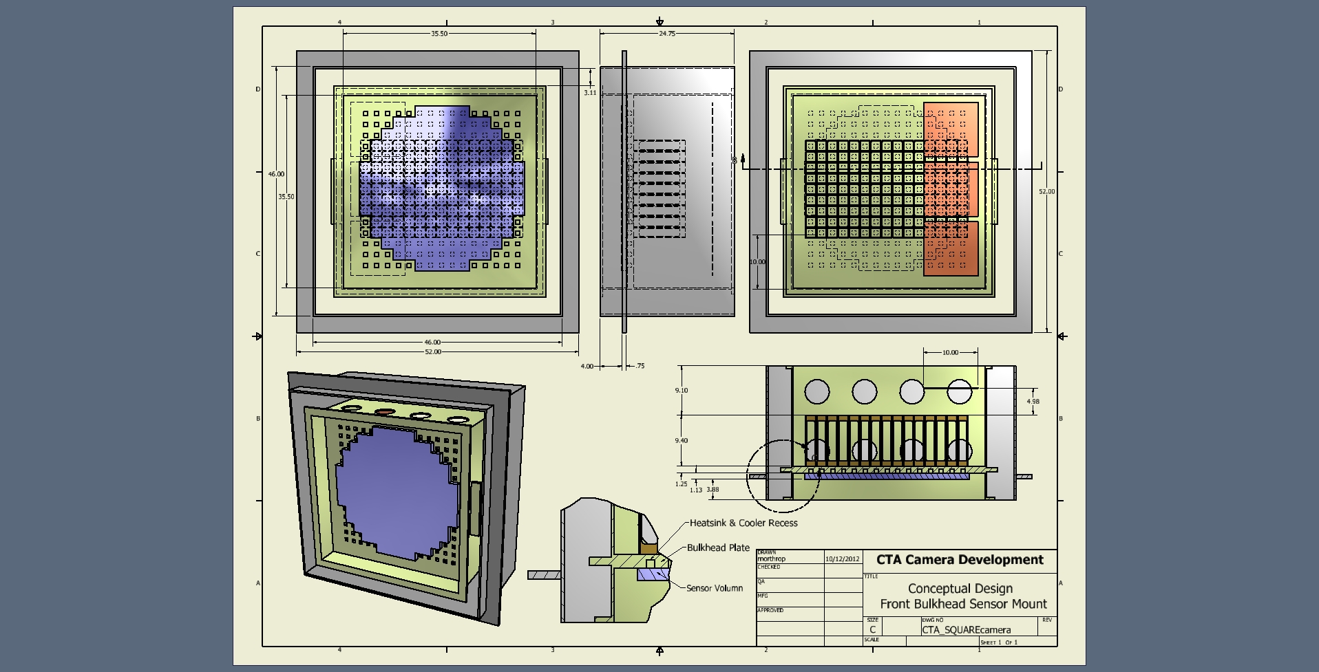 27 Square Camera with outer enclosure/structure-mount flange and inner enclosure/bulkhead |
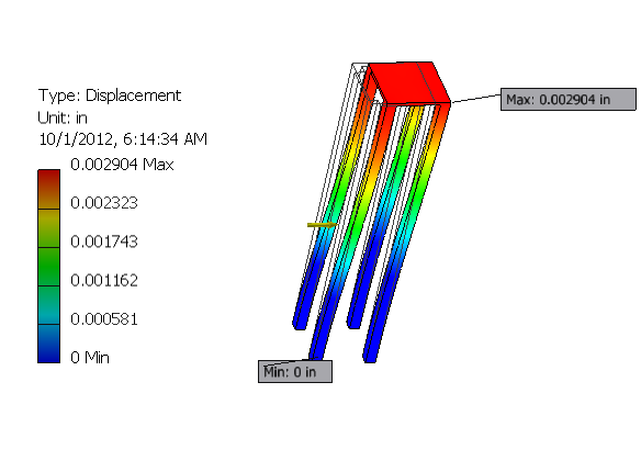 28 SiPM mounted to columns-Deflection under 2 lb. UDL side loading |
 29 |
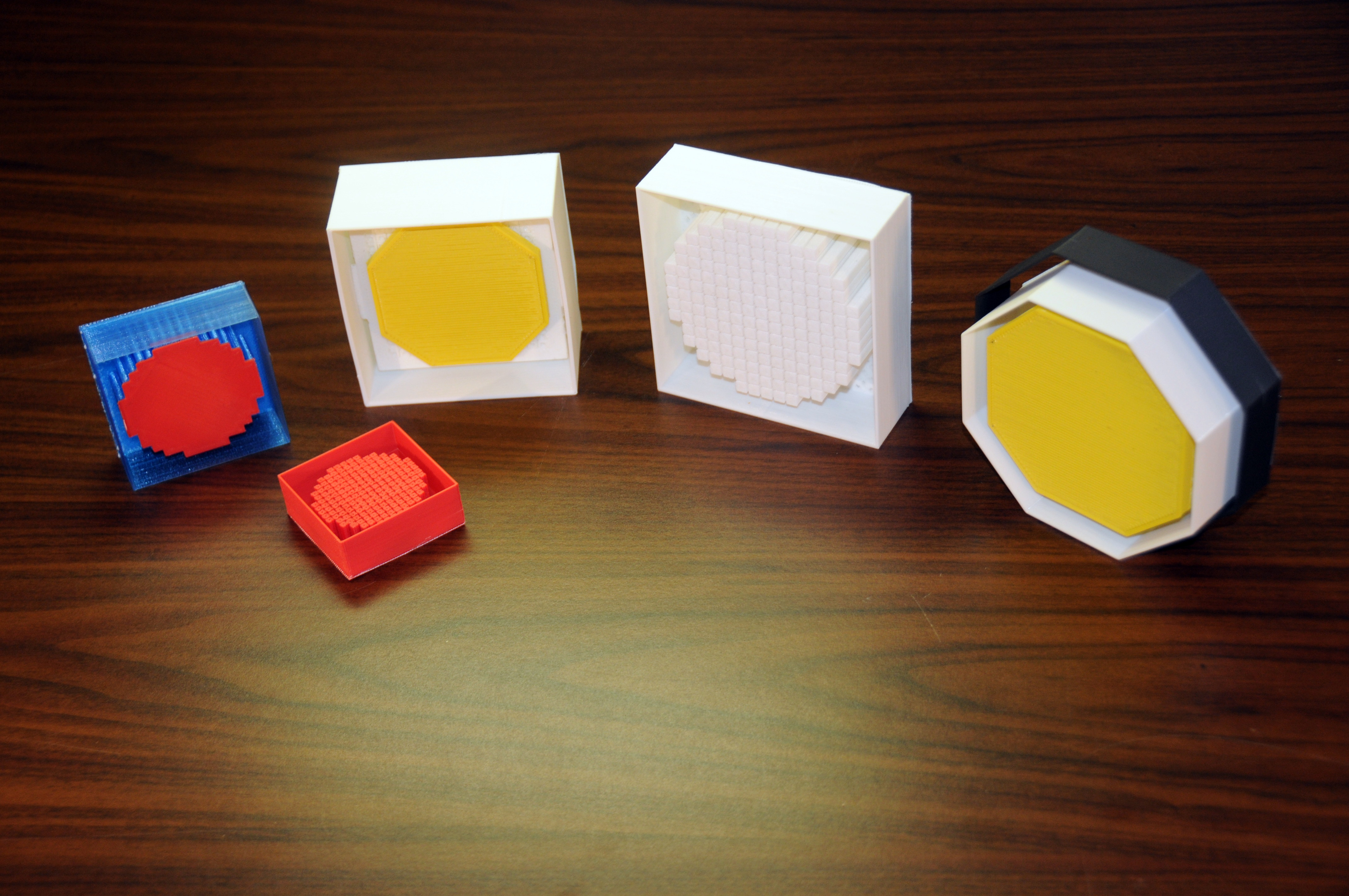 30 Scale models of four camera design types |
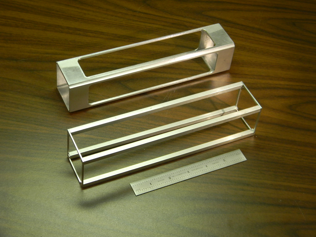 31 Full scale prototypes of two versions for the FEE/Sensor support cage |
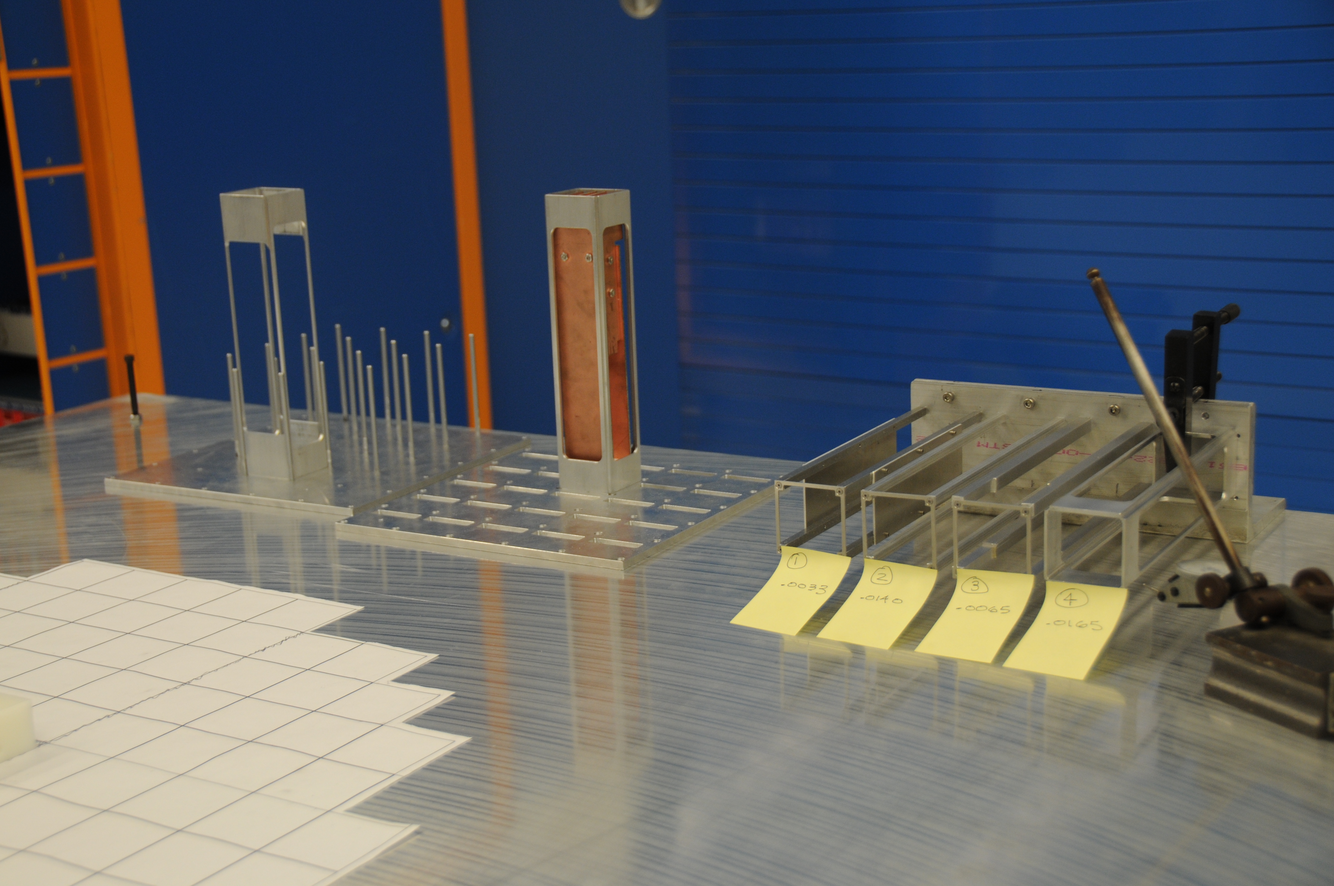 32 FEE/cage structure protypes , 4 versions, showing deflections under 2 lb. UDL |
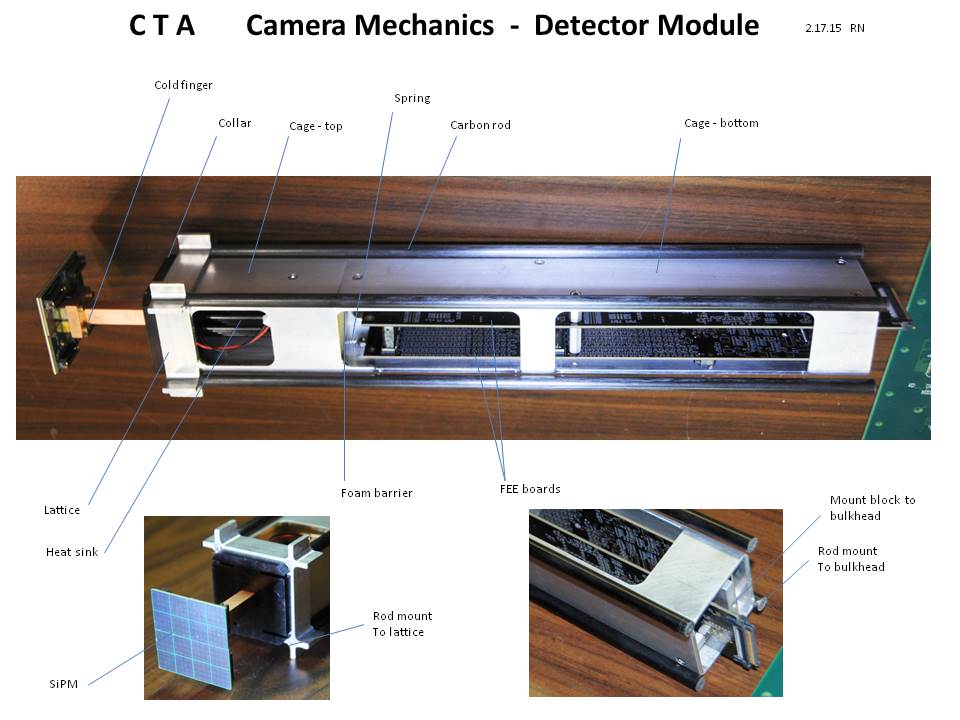
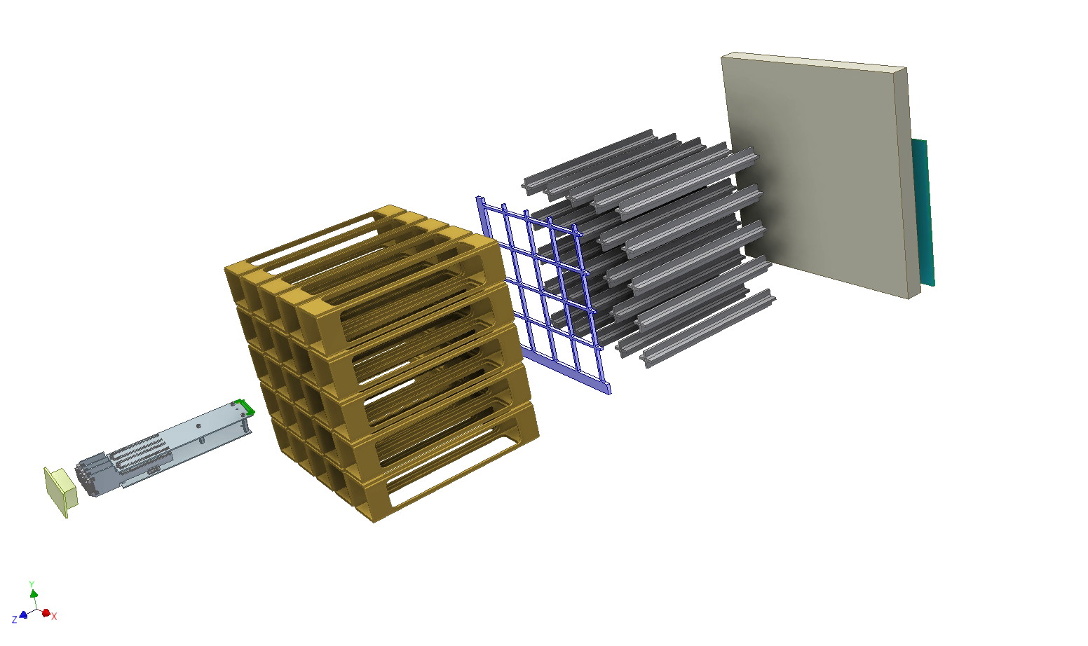 33 From left- SiPM with block & cooler assembly, FEE, cages, lattice, post, back plate, mother board. |
 34 |
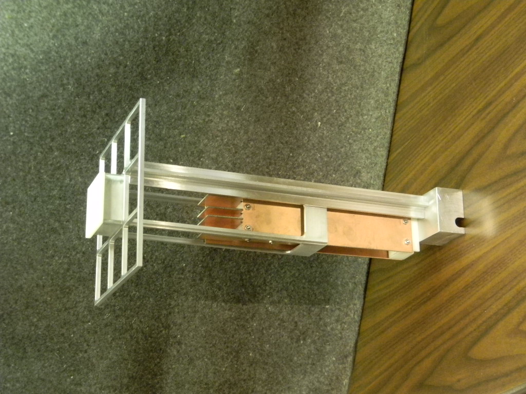
 35 |
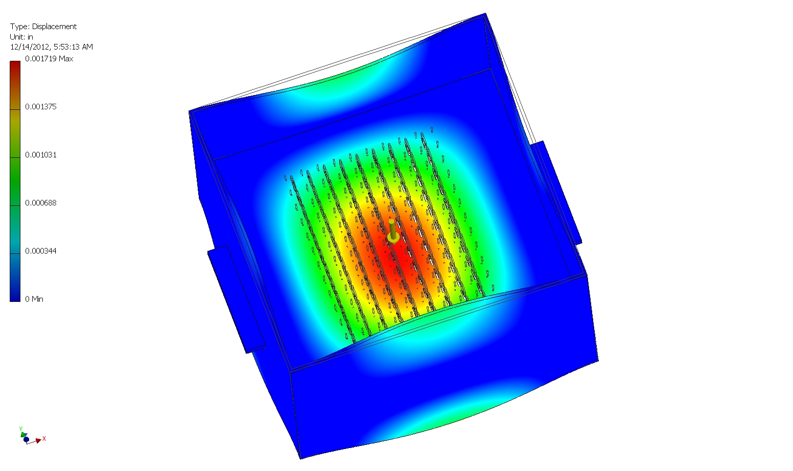
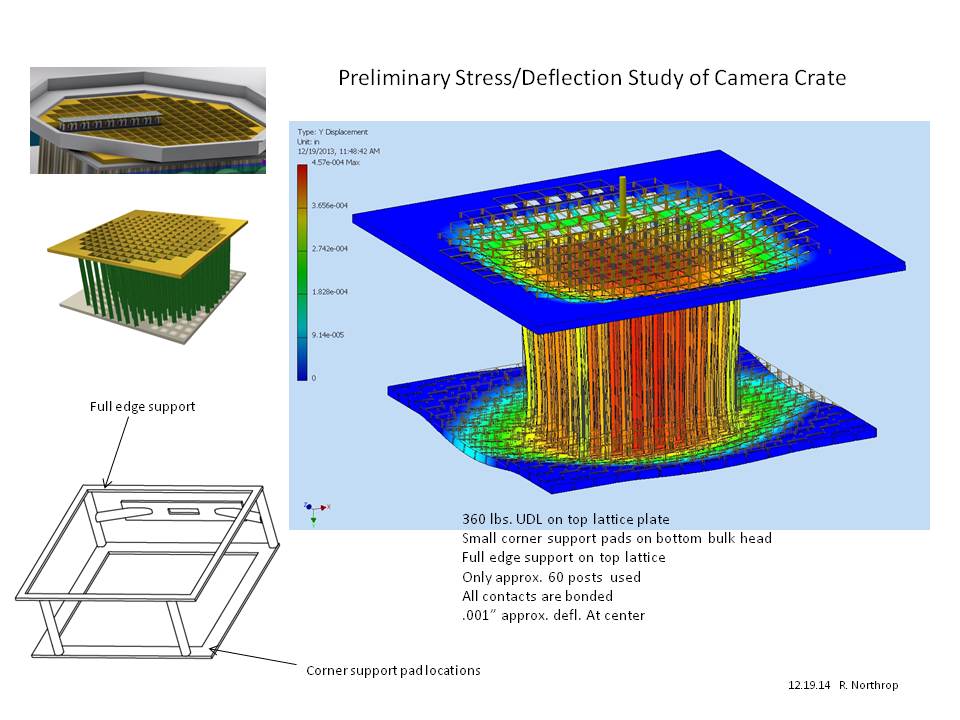
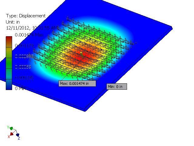 36 0.0015 in. center deflection under 600 lb. UDL |
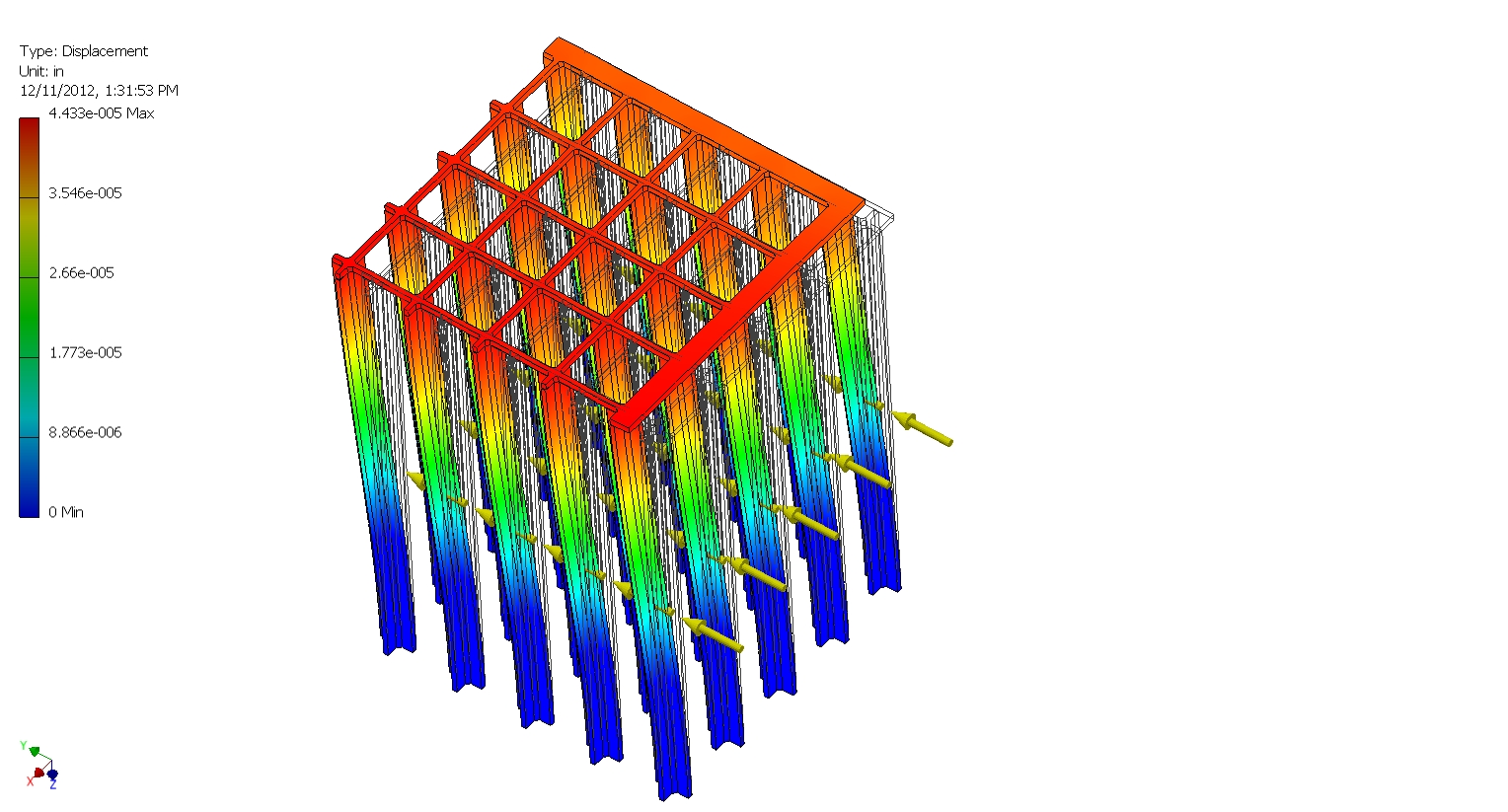 37 A portion of the FEE support post and lattice assembly under 1 lb. UDL (each post) |
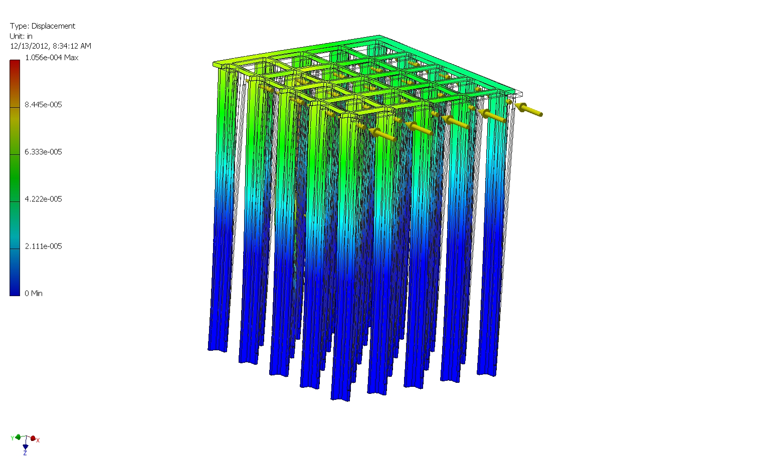 38 A portion of the post & lattace assembly under 1 lb. top loading on all 25 posts |
 39 inner enclosure deflection under 600 lb. UDL load |
 40 |
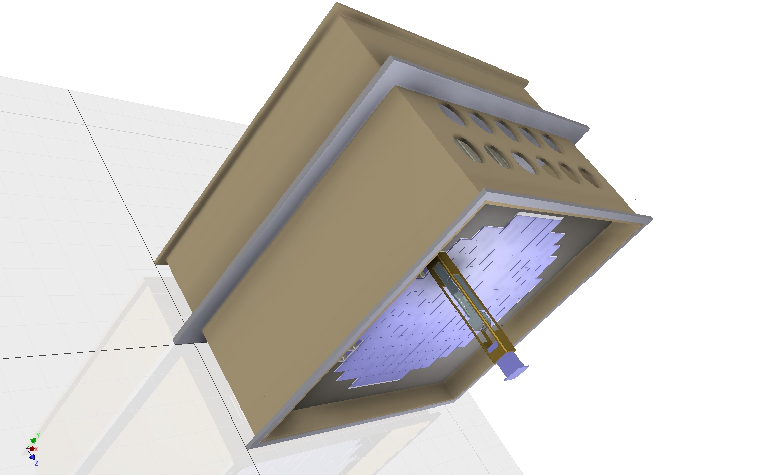
 41 Mockup shows the 1.25” Bulkhead plate (far right) with groove for 10 mm dia. copper tubing, the new X post, and the new front lattice. It also shows the model of the FEE , previous shorter cage, and the top SiPM sensor (far right) |
 42 |
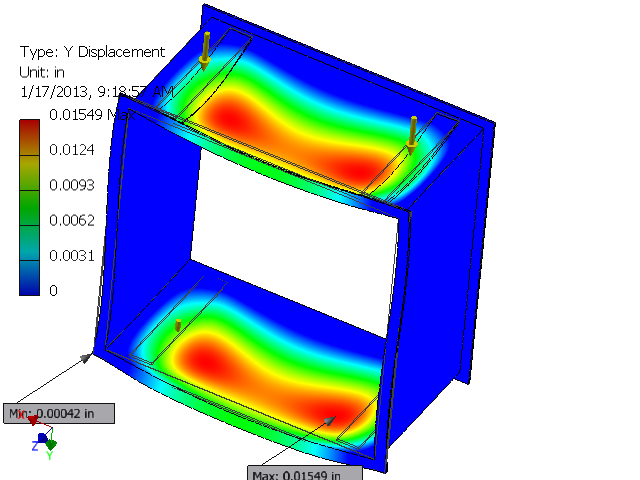
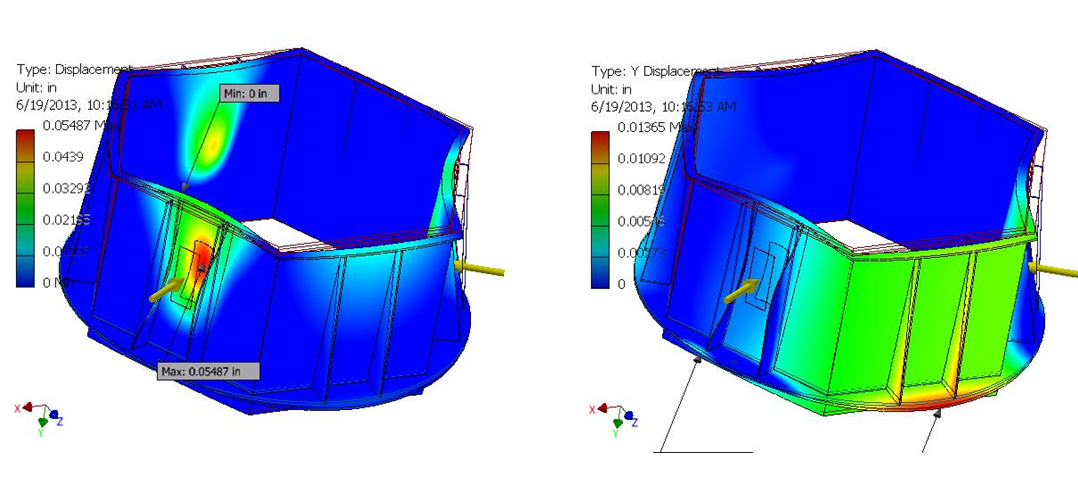
 43 |
 44 Z adjustment deflections on innner enclosure – 120 lbs. on each of 4 bars |
 45 5th generation camera concept – square inner enclosure with outside enclosure corners chamfered to redude mirror shadowing |
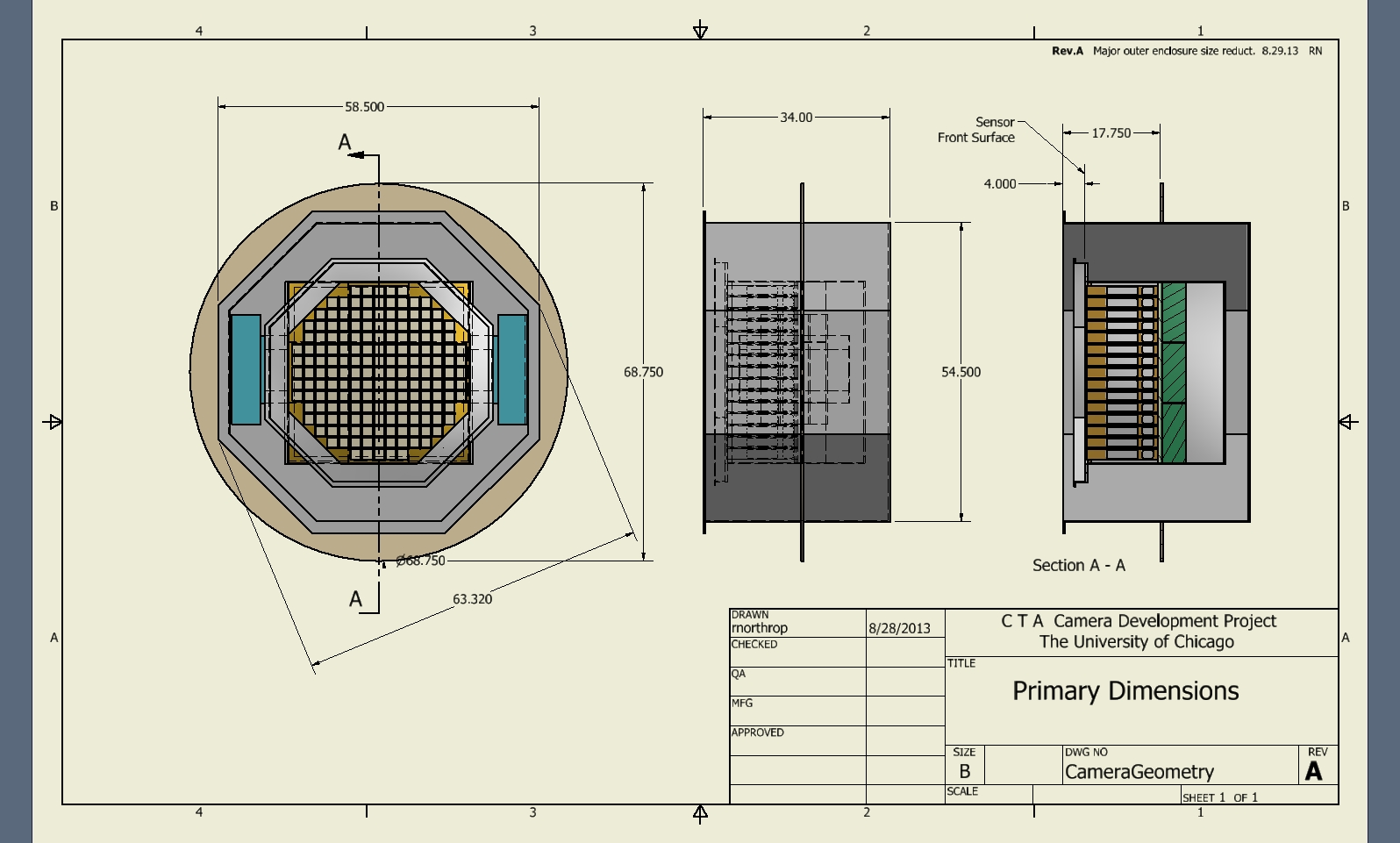
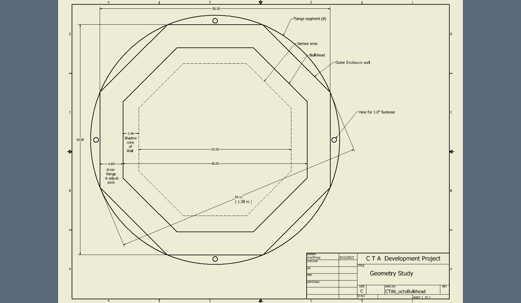 46 New camera geometry to reduce mirror shadow to 1.4 meters |
 47 |
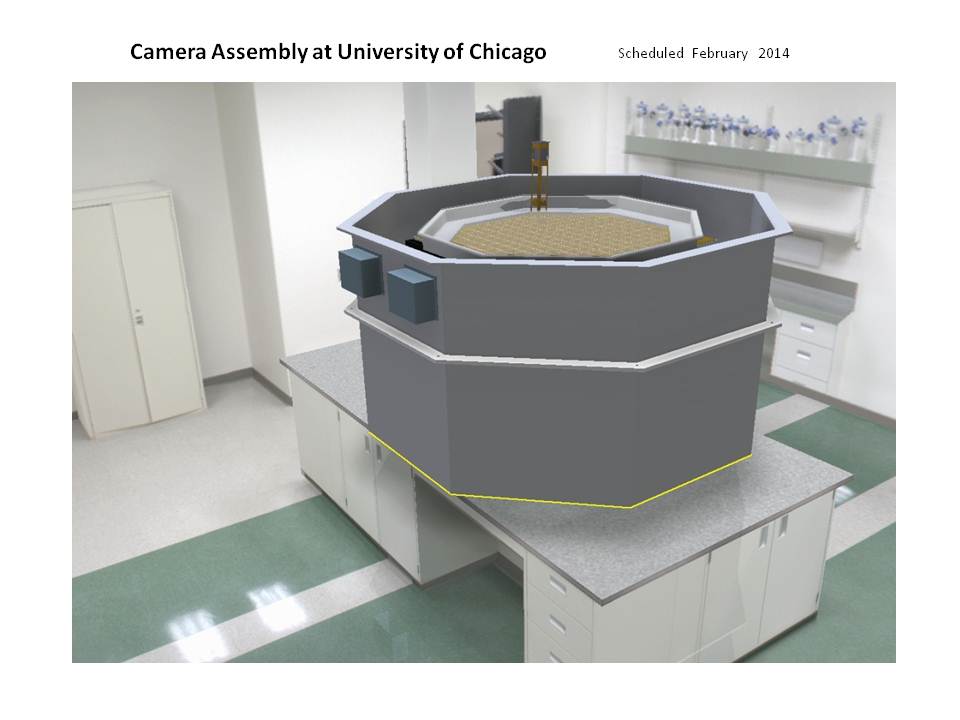
 48 |
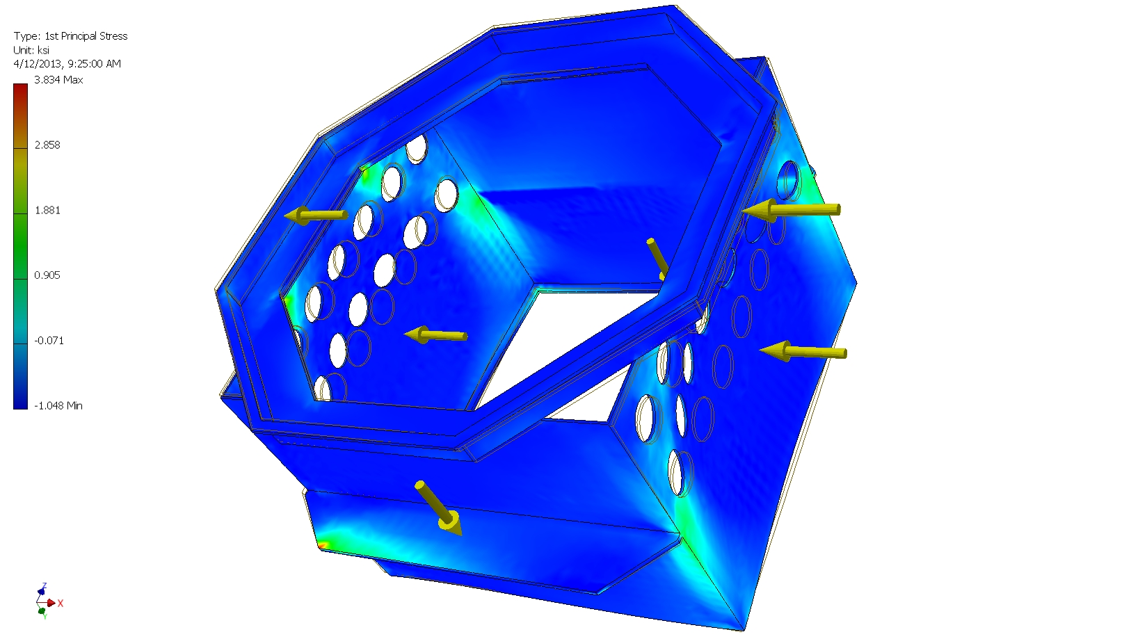 49 Inner enclosure stress study with four 300 lb. UDL side loads and 2 two 200 ld. UDL vertical loads |
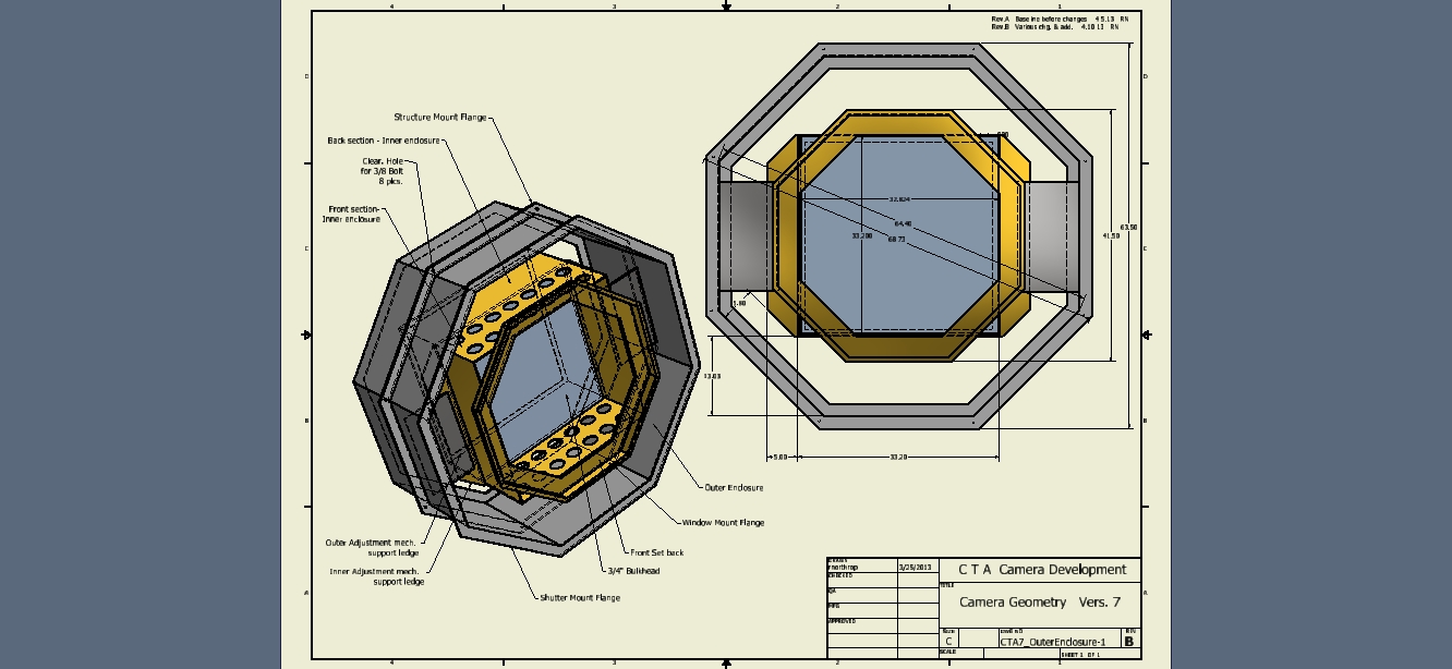
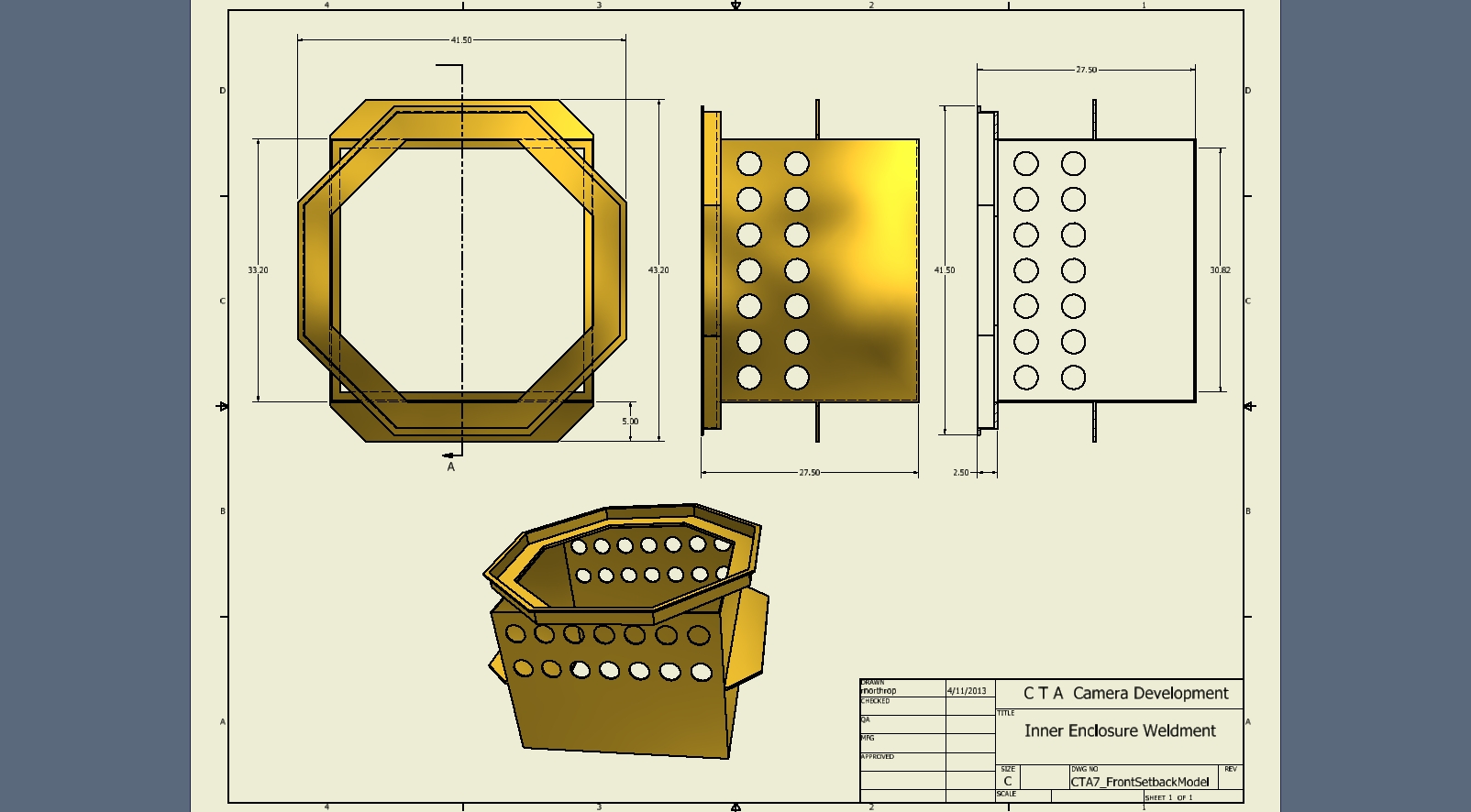
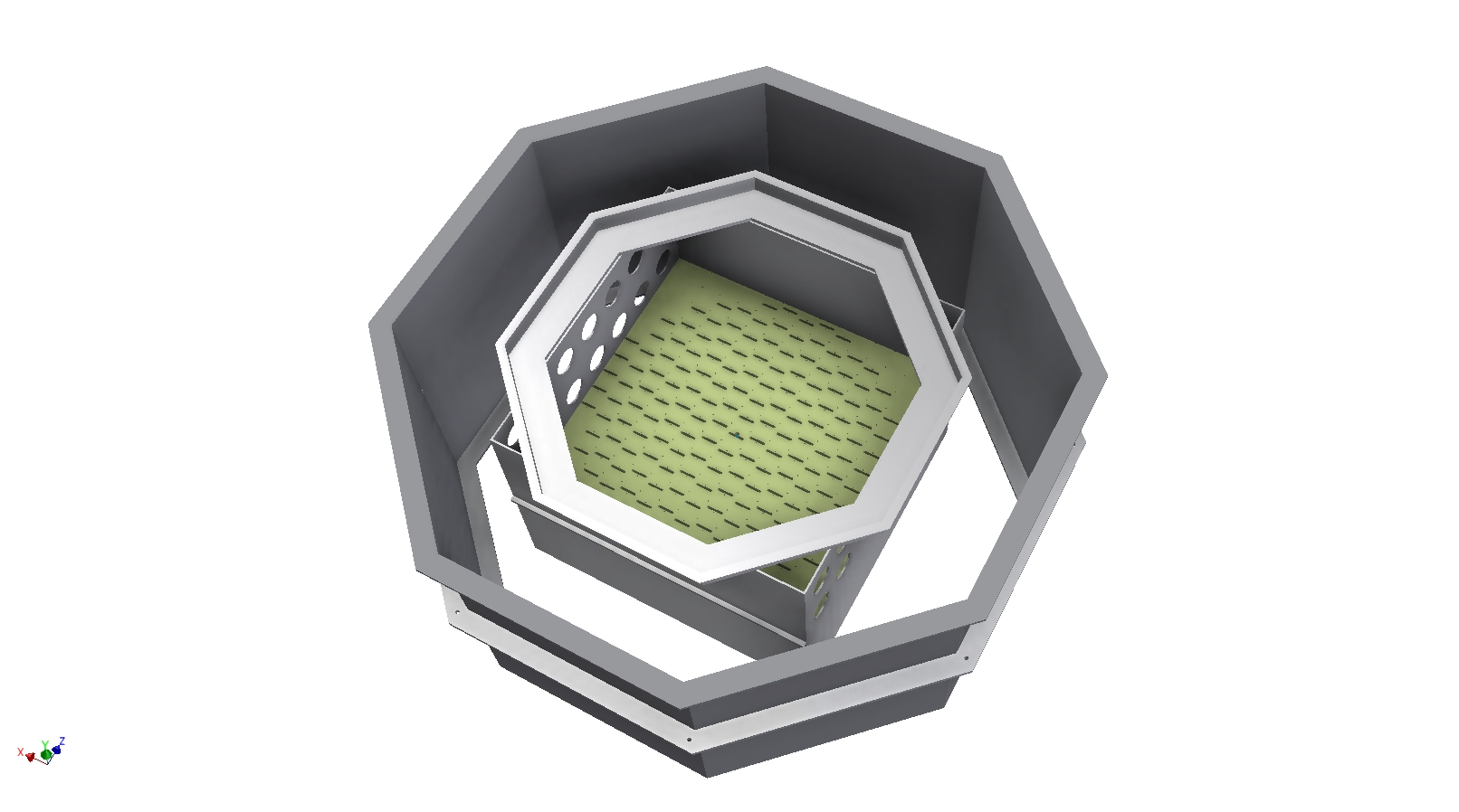 50 inner enclosure showing bulkhead penetrations,available zone for adjustment mechanisms, and outer enclosure |
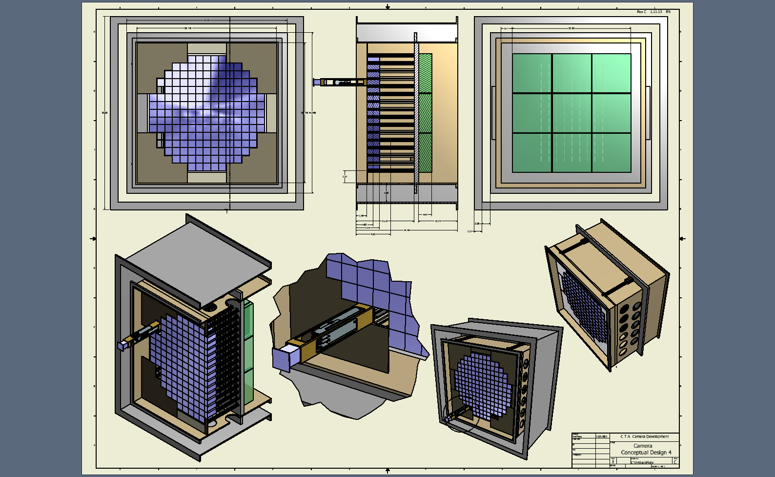
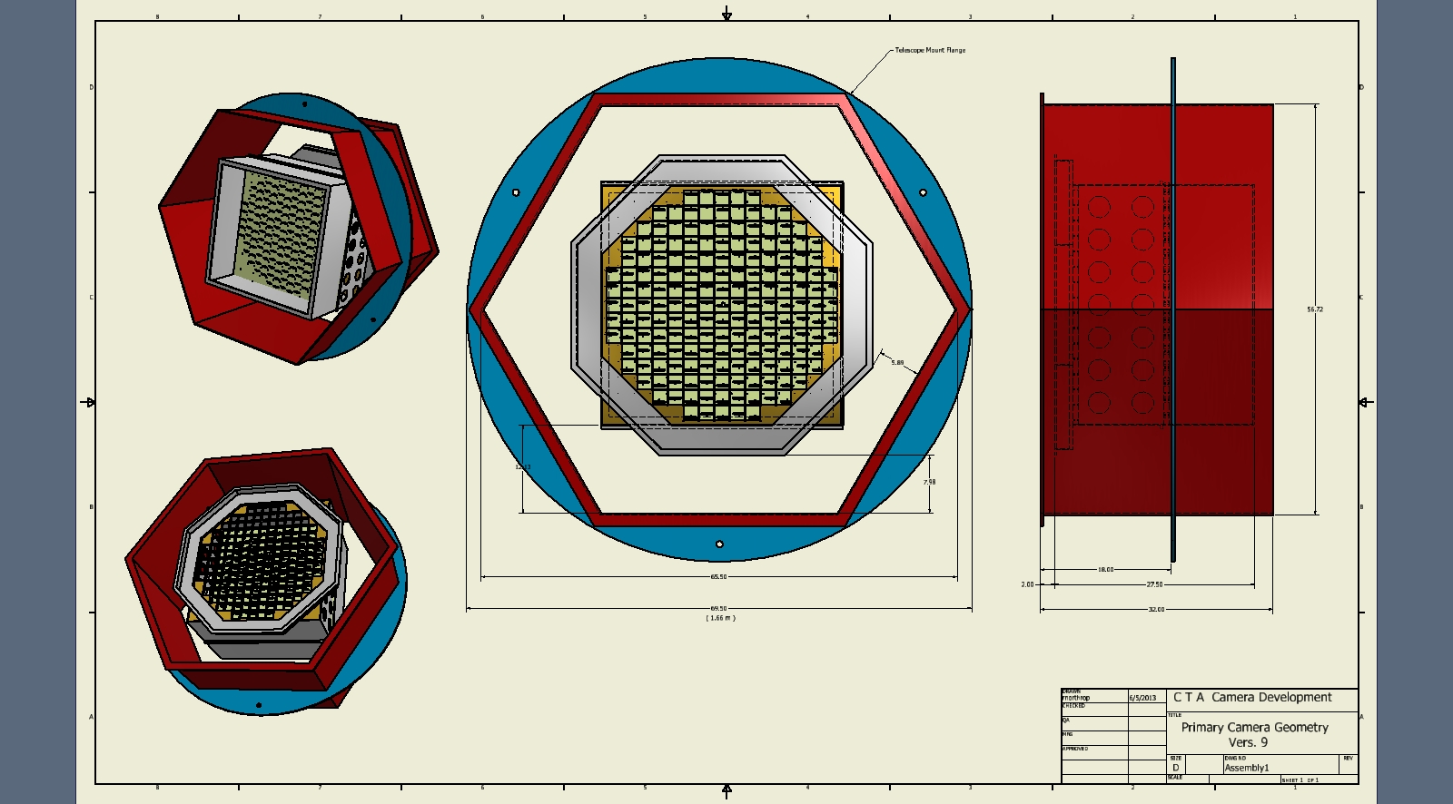
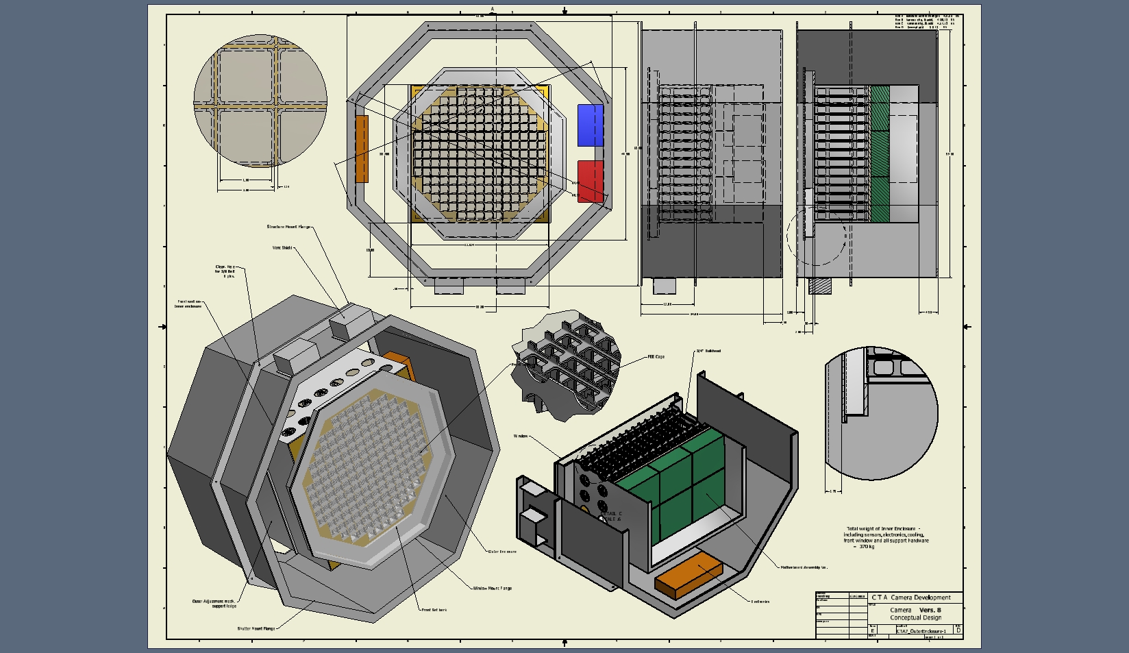 51 Camera conceptual design - Version 8 |
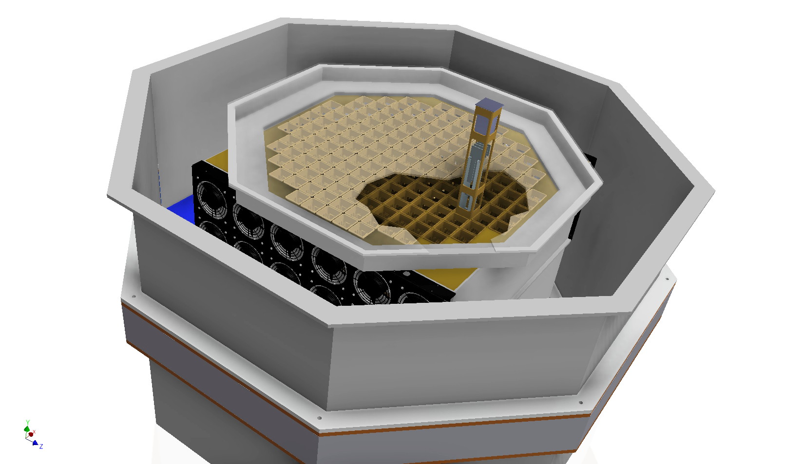 52 Front camera view showing SiPm sensor module prior to insertion, cooling fans, and telescope structure interface flange |
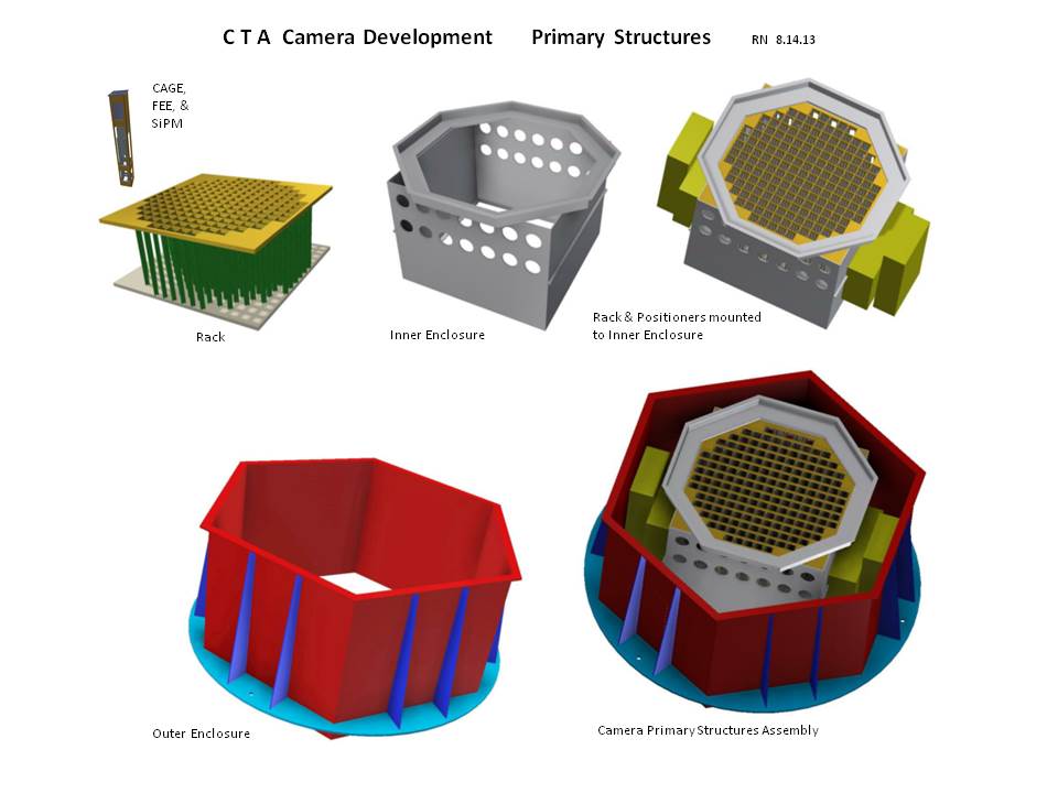
 53 |
 54 Preliminary design for first prototype at Chicago -October 2013 |
 55 |
 56 Hexagon Camera Geometry with 3 point mount |
 57 Front lattace under 16 center post push @ 4 lbs. = 64 lb. |
 58 Outer enclosure deflections & main ring lift with hexapod mount pad loading @ 600 lbs. x 3 @ 120 degrees |
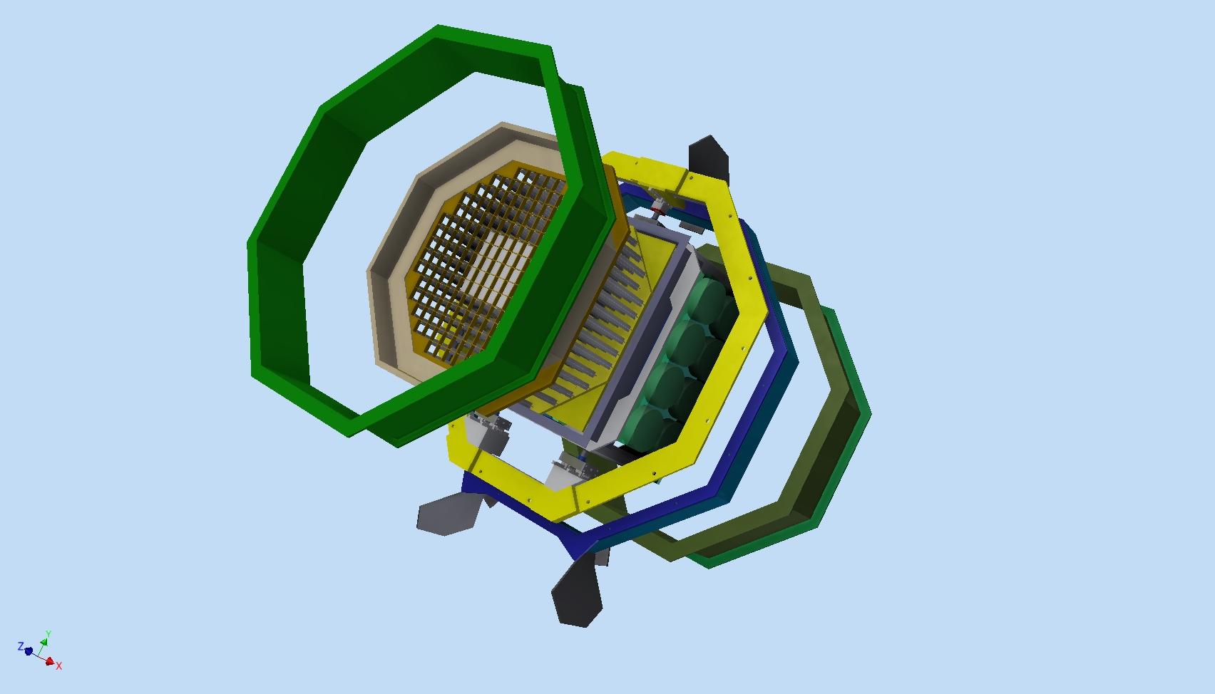
 59 Camera Main subassemblies – exploded view |
 60 |
 61 Camera position stages (shown in green) |
 62 |
 63 |
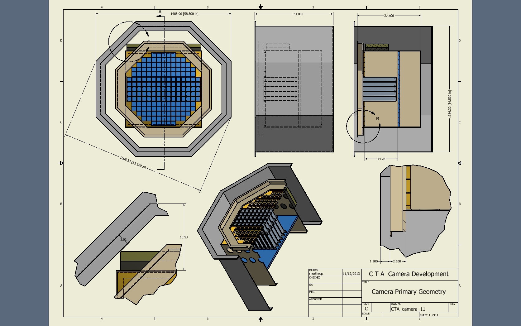
 64 |
 65 |
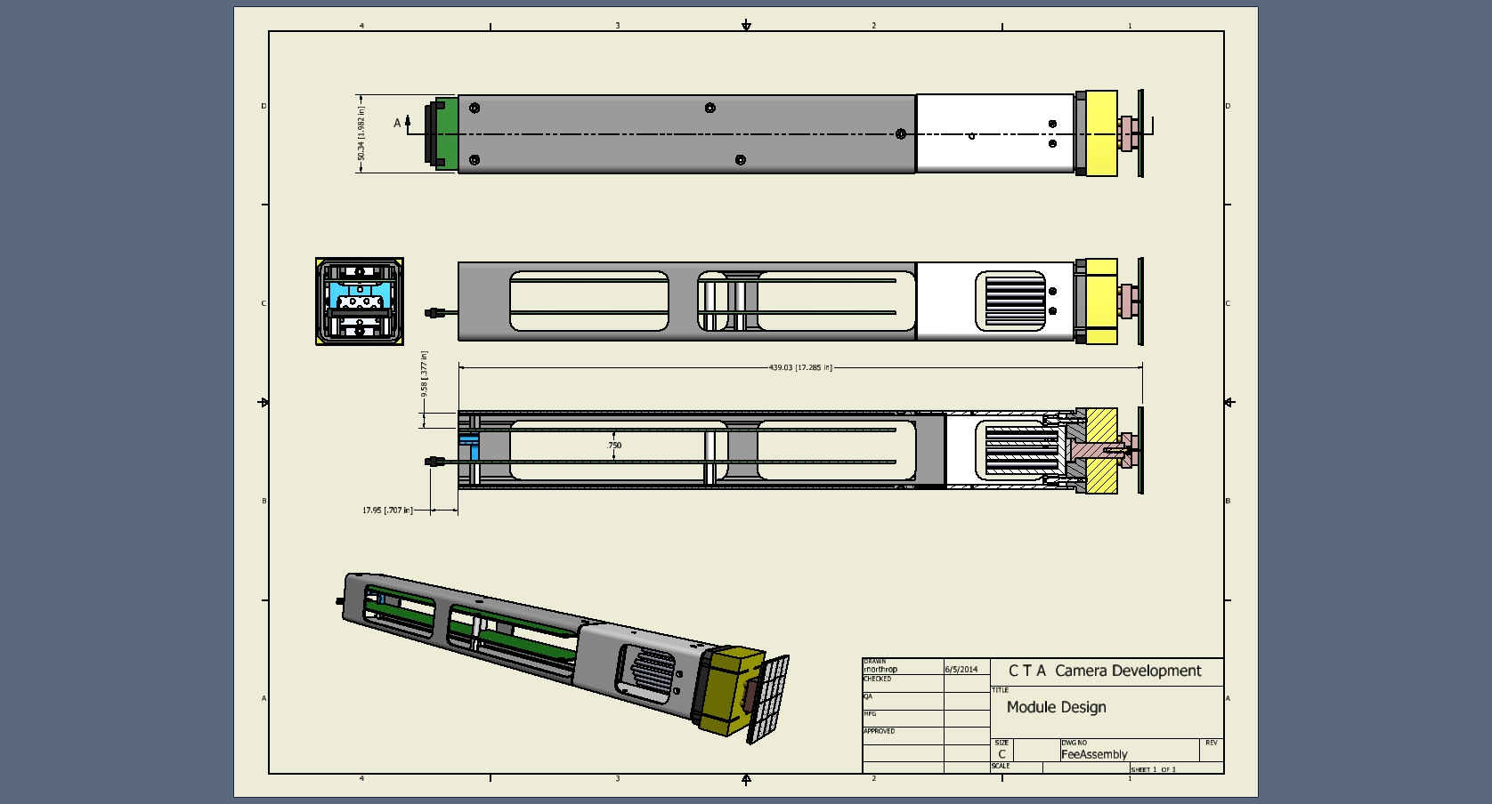
 66 Camera front Elements – sensor module,lattace,positioner ring + telescope mount gussets, & cooling unit |
 67 |
 68 |
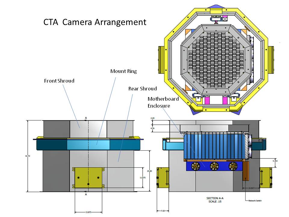
 69 SiPM Sensor design |
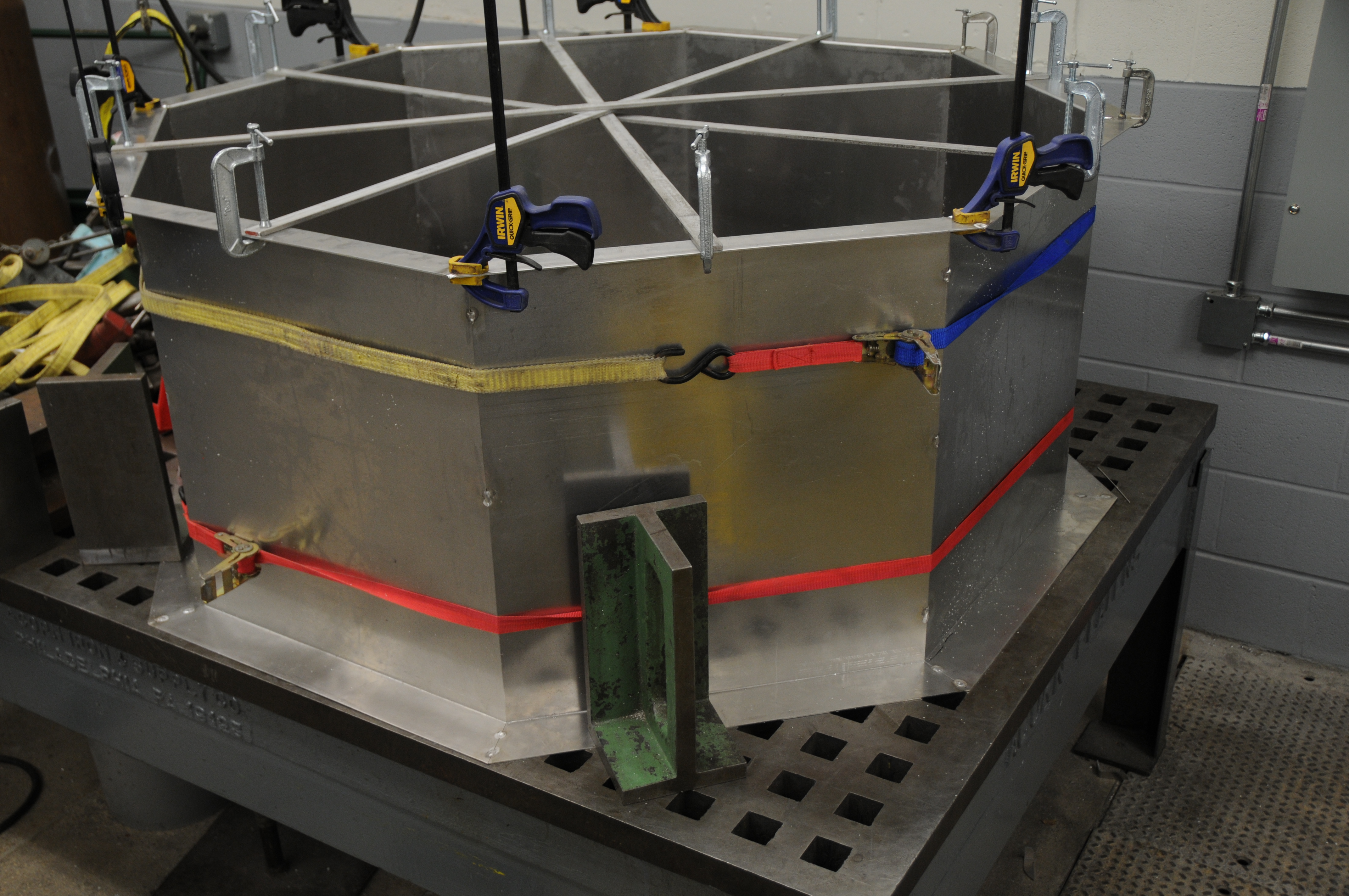
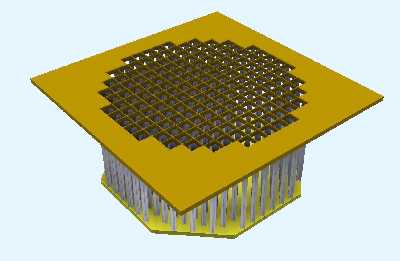 70 Camera crate with Octagon bulkhead plate |
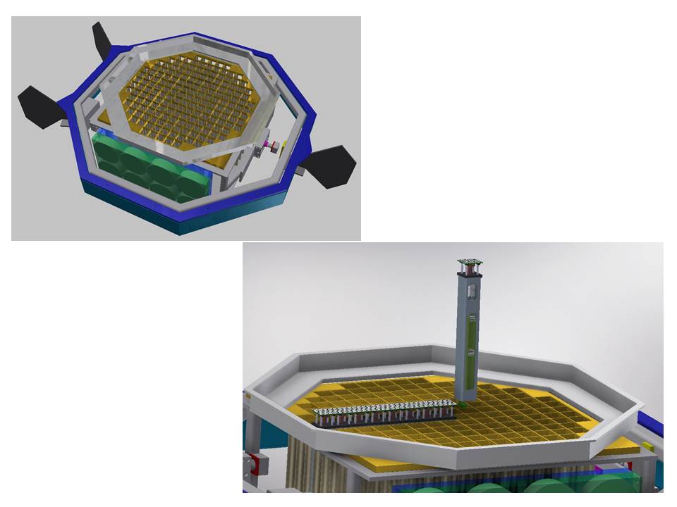
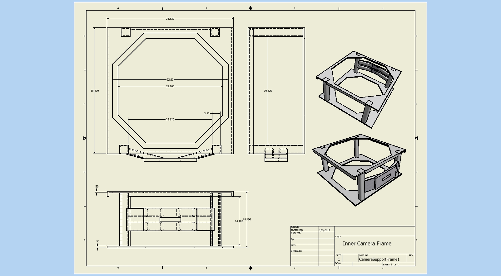
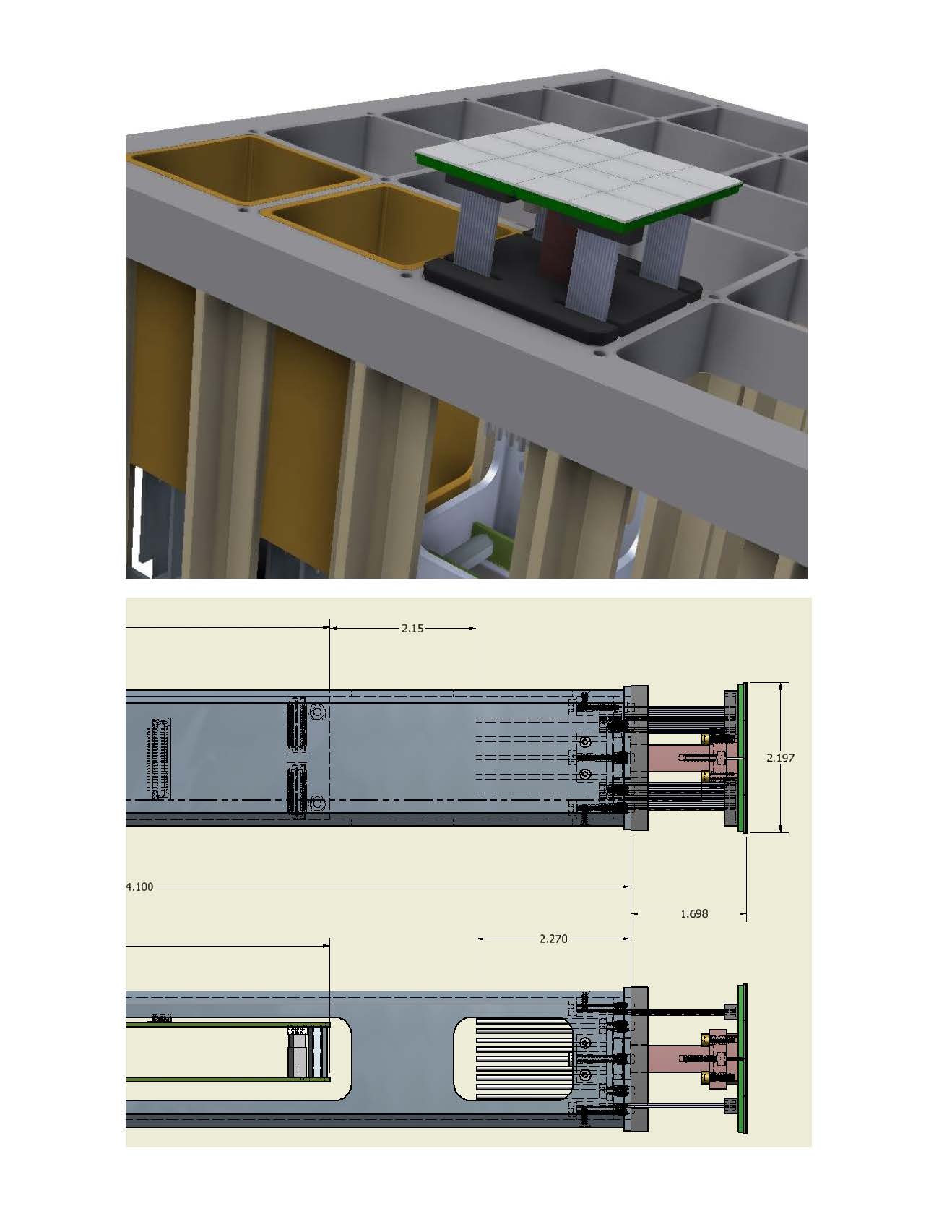
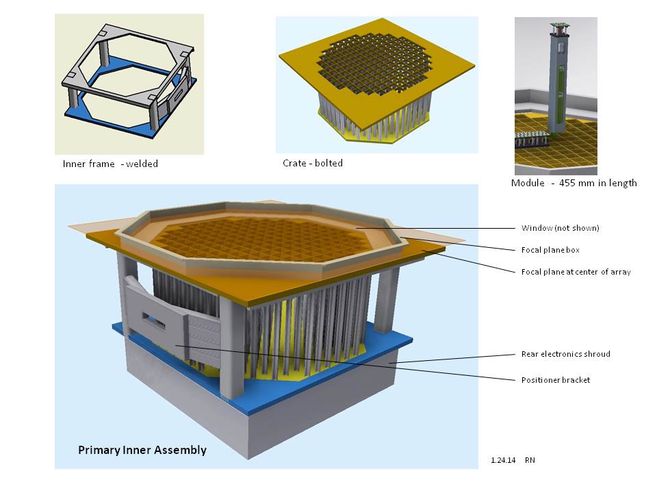
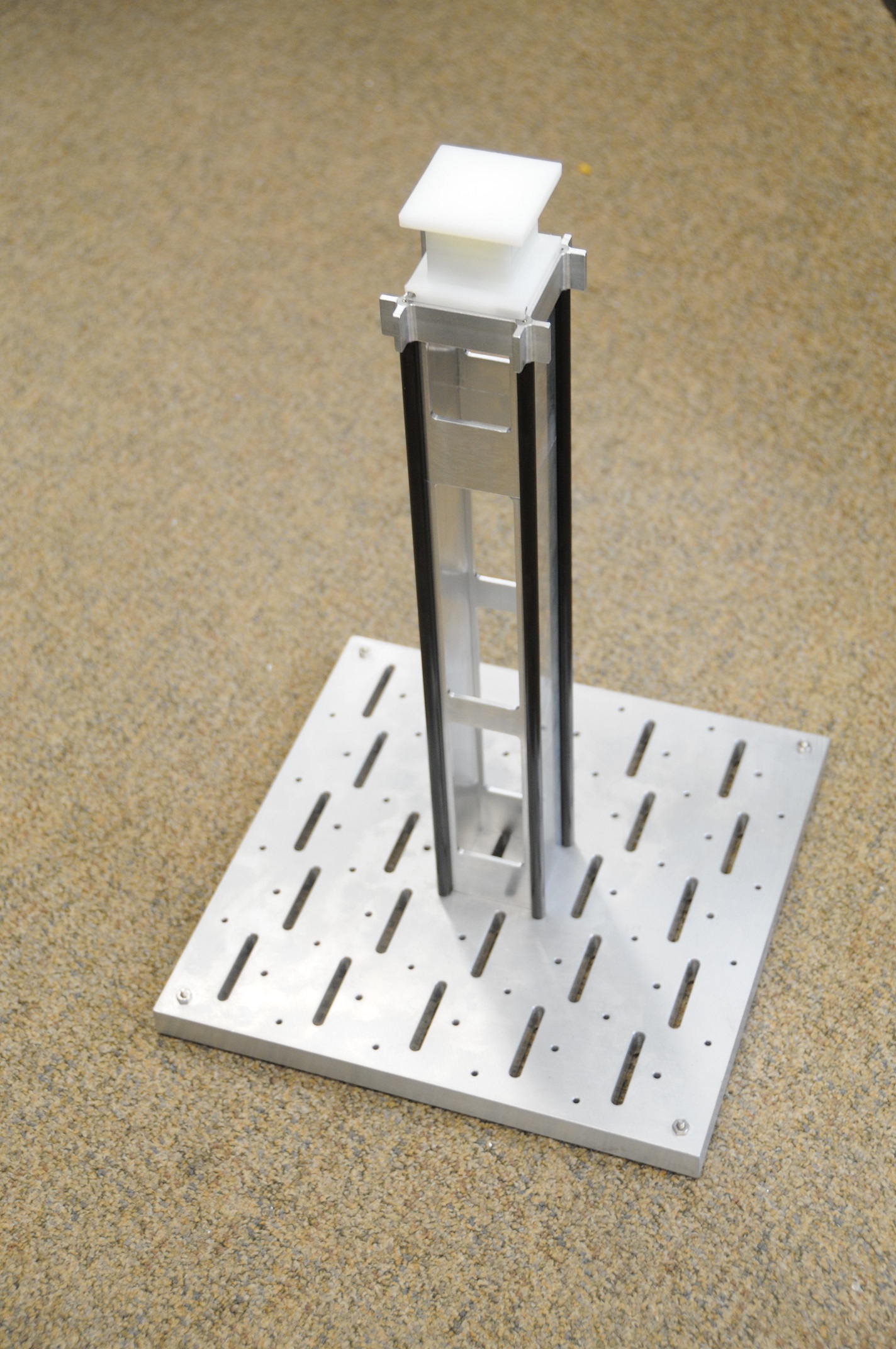
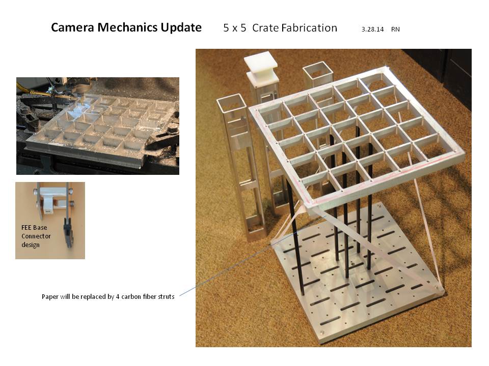
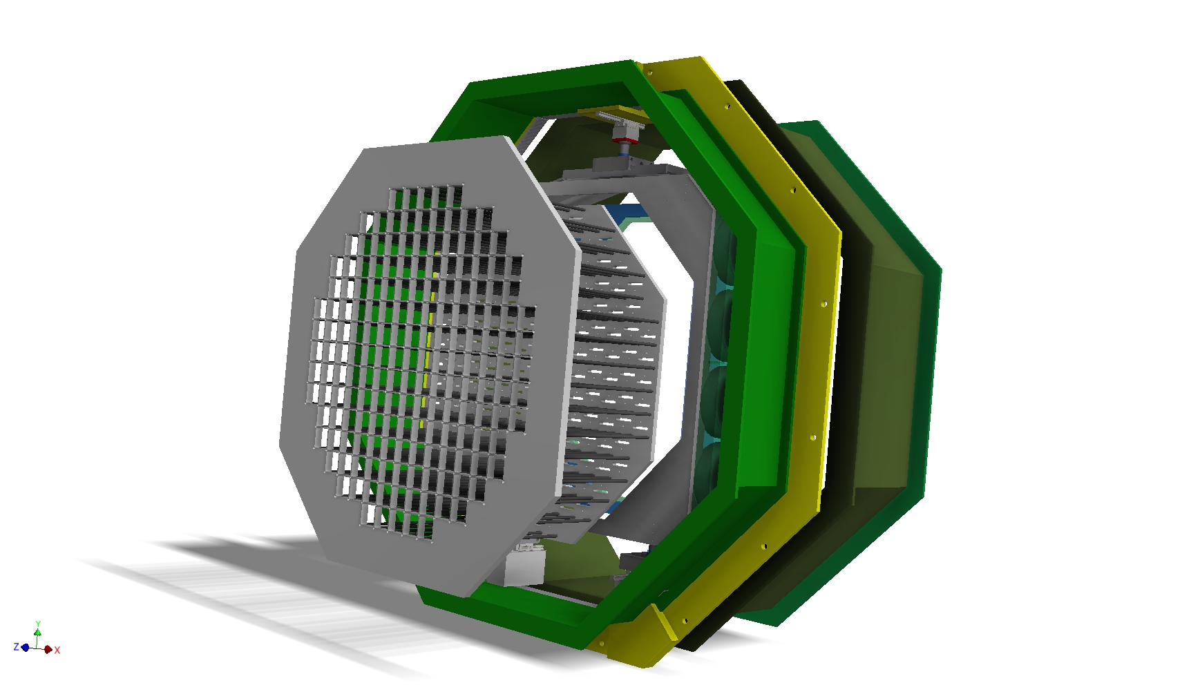
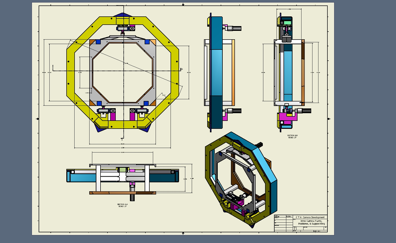
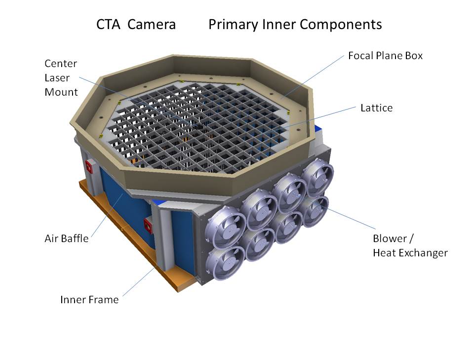
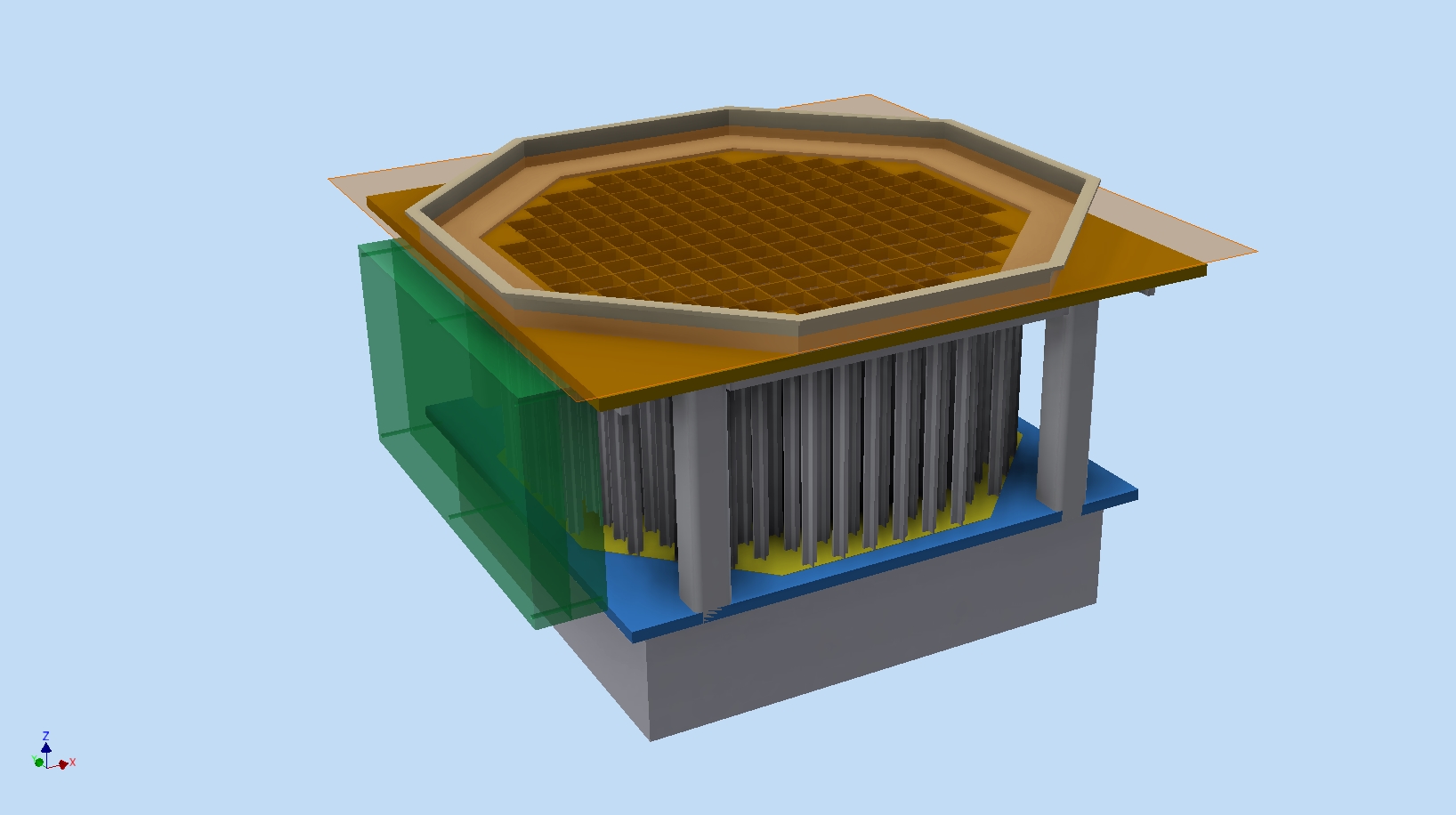 71 Primary Inner Camera Assembly |
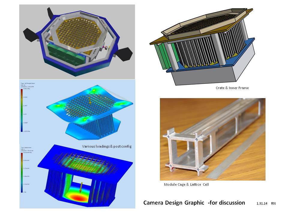
 72 graphic for Jan.24 mechanical telecon |
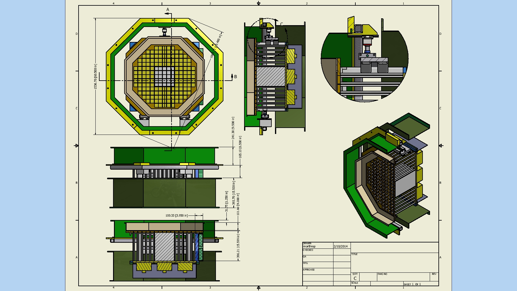
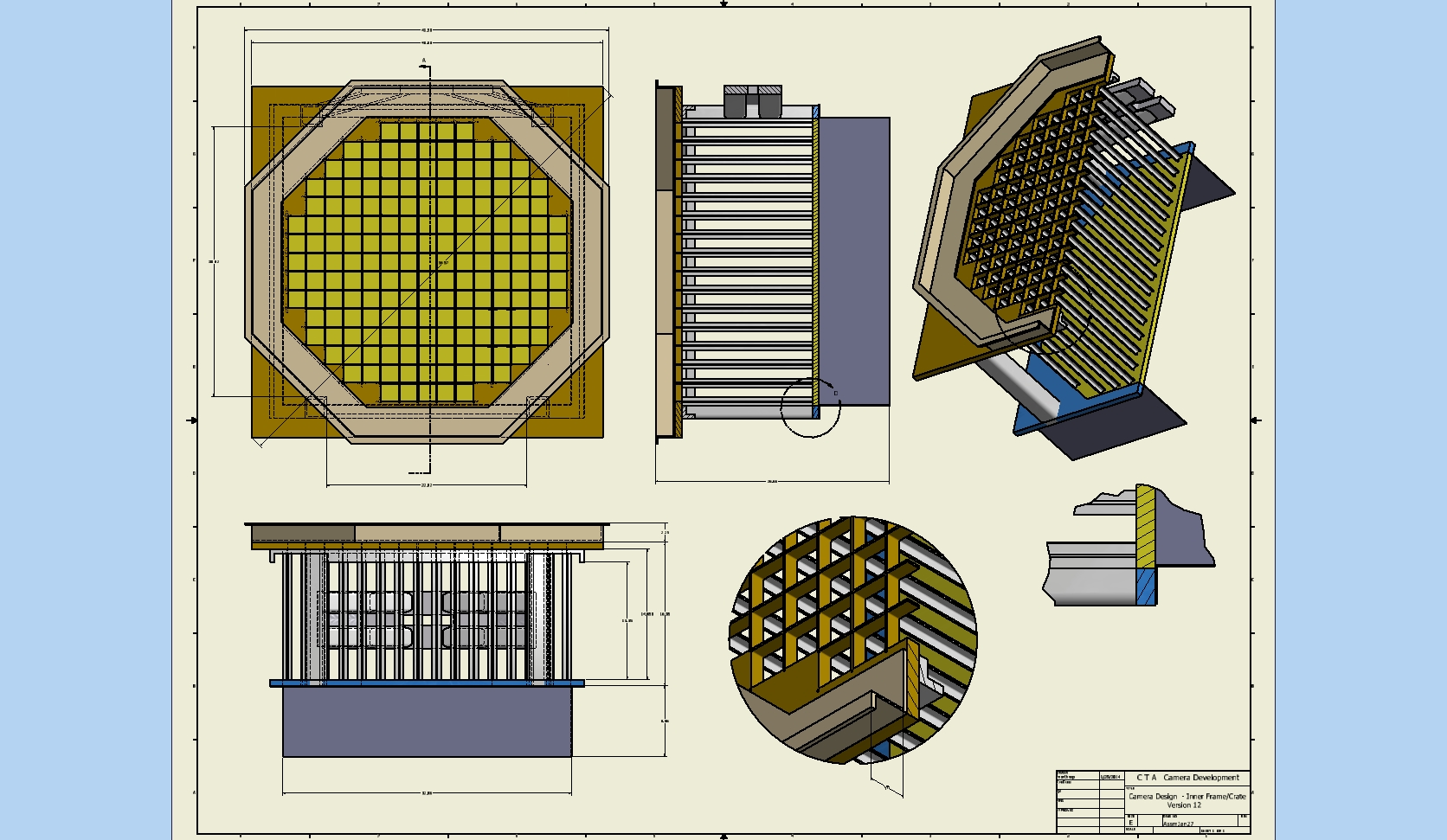 73 Camera design version 12 |
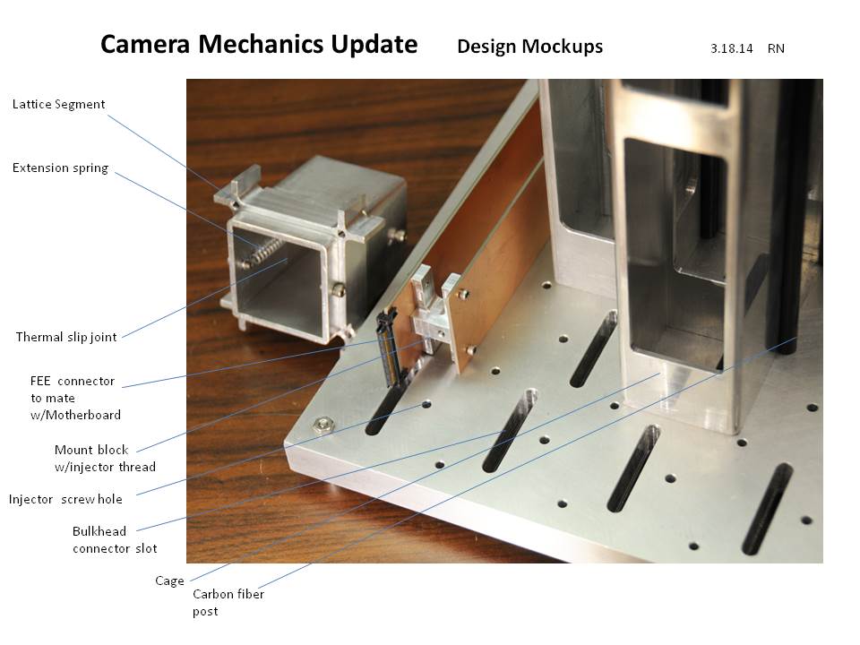
 74 |
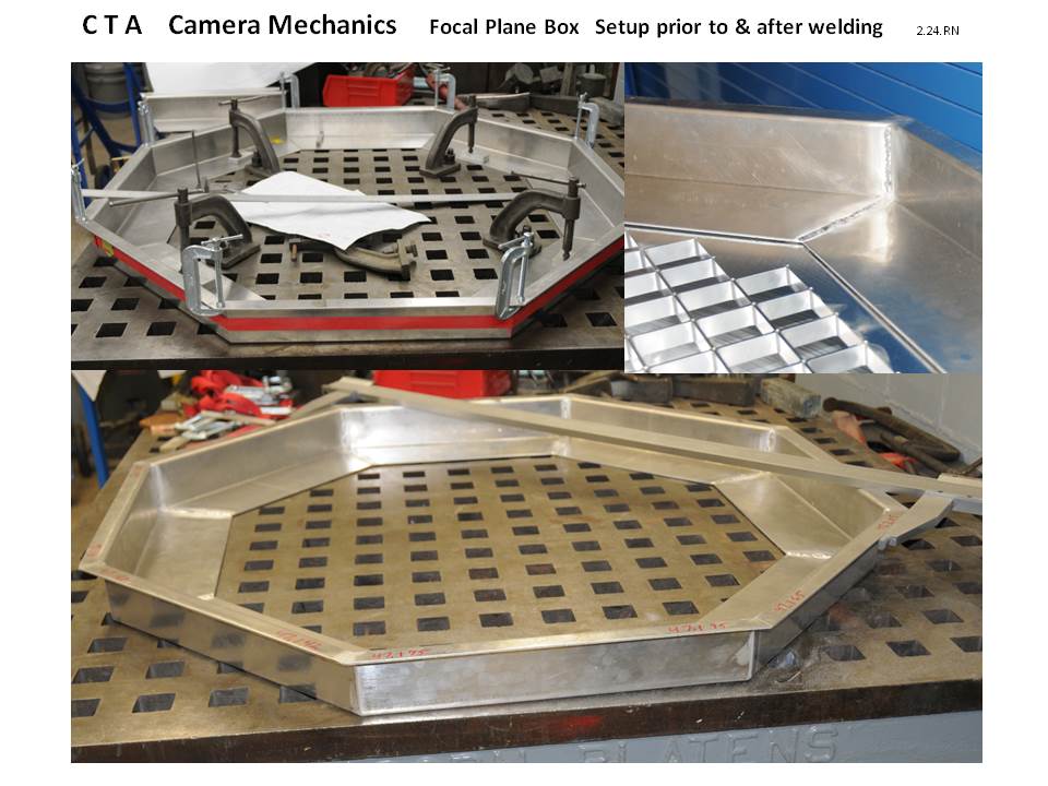
 75 CTA camera arrangement - prototype baseline Feb. 19, 2014. |
 76 Expoded Prototype camera showing major assemblies-Top outside enclosure, Crate (focal plane box,rack,rear elect.shroud), OSS mount ring, and rear outside enclosure. |
 77 Start of 5 x 5 camera module using 4 carbon fiber posts,center FEE cage, sensor mockup, and bulkhead. |
 78 |
 79 |
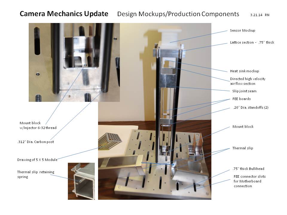 80 Presentation for Internal Camera Design Update meeting March 21, 2014 |
 81 |
 82 |
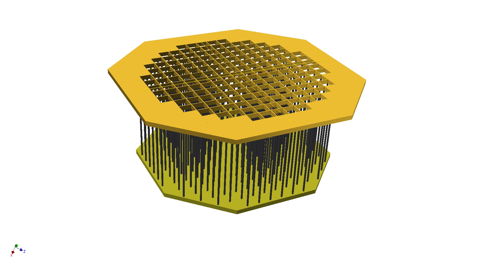 83 Revised Camera crate geometry and showing new carbon fiber posts |
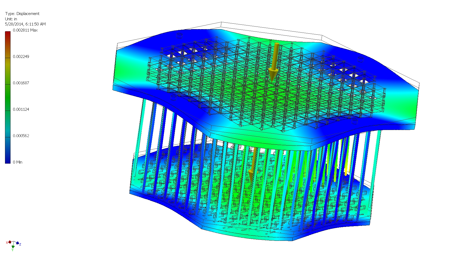 84 deformation study with 180 lb.UDL on the top lattice and 180 lb.UDL on bottom bulkhead – supported by 4 top ½ bolts |
 85 |
 86 |
 87 |
 88 |
 89 |
 90 |
 91 Prototype Camera Arrangement |
 92 |
 93 |
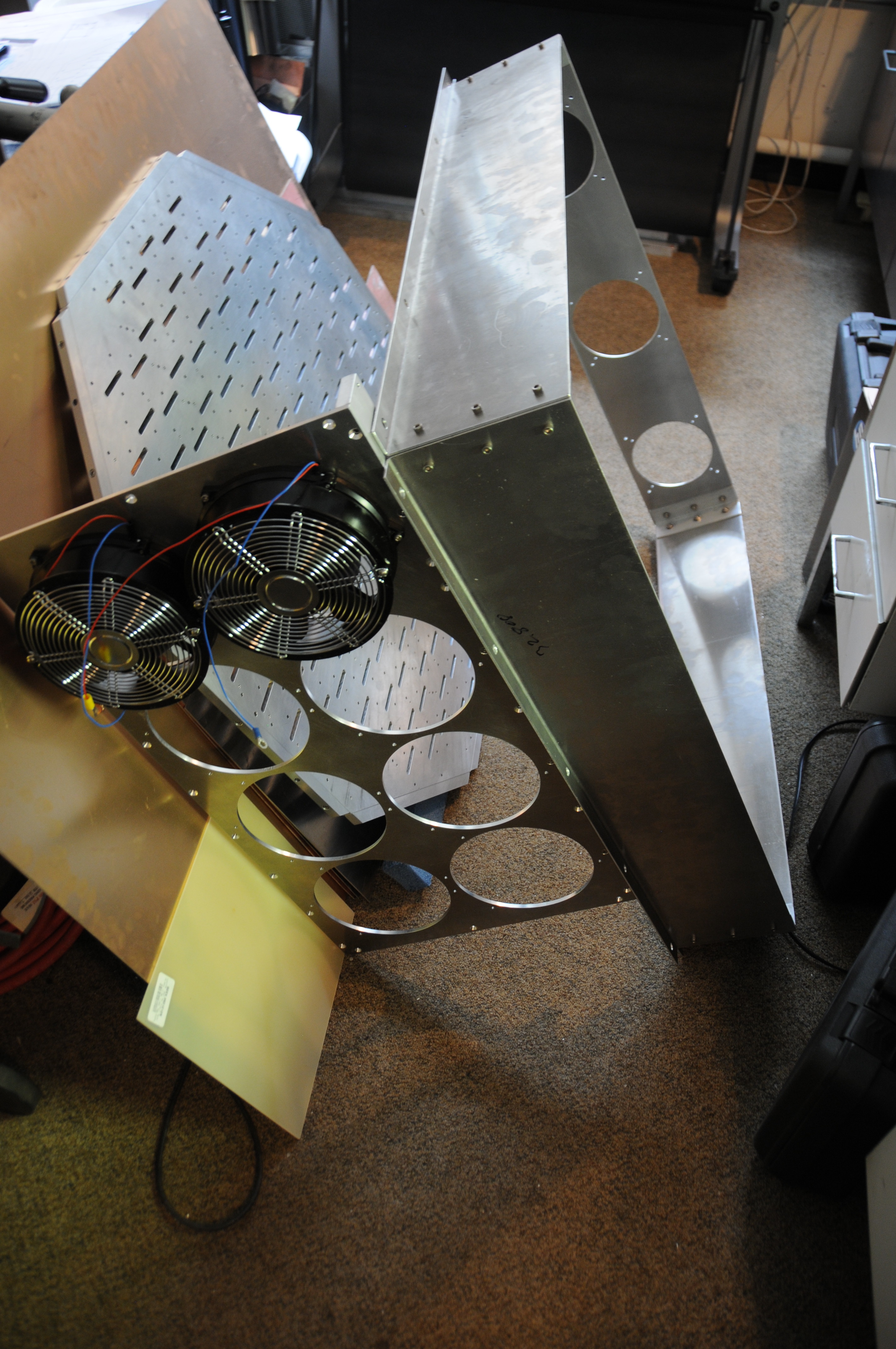
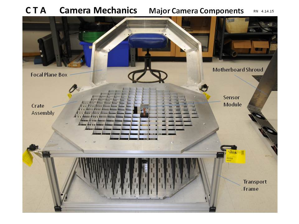
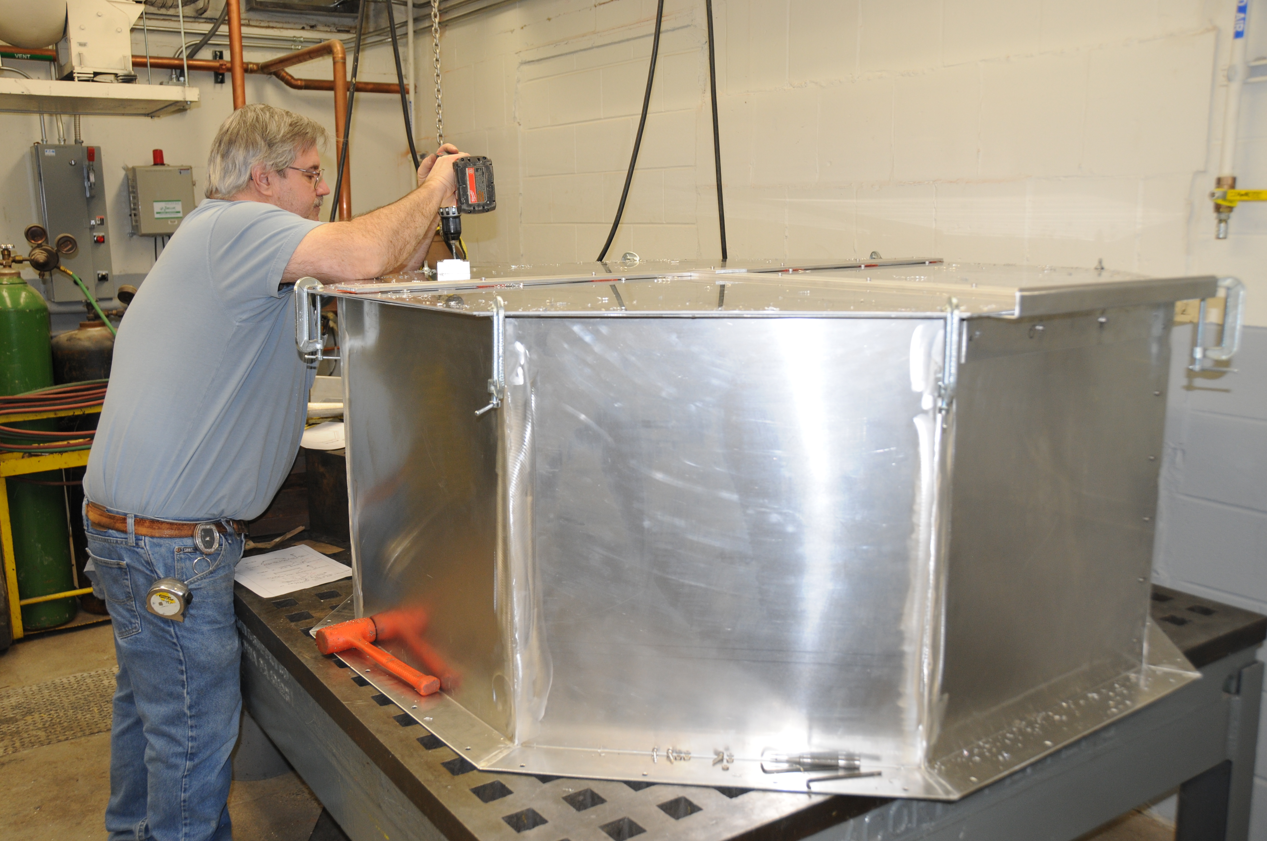
 94 |
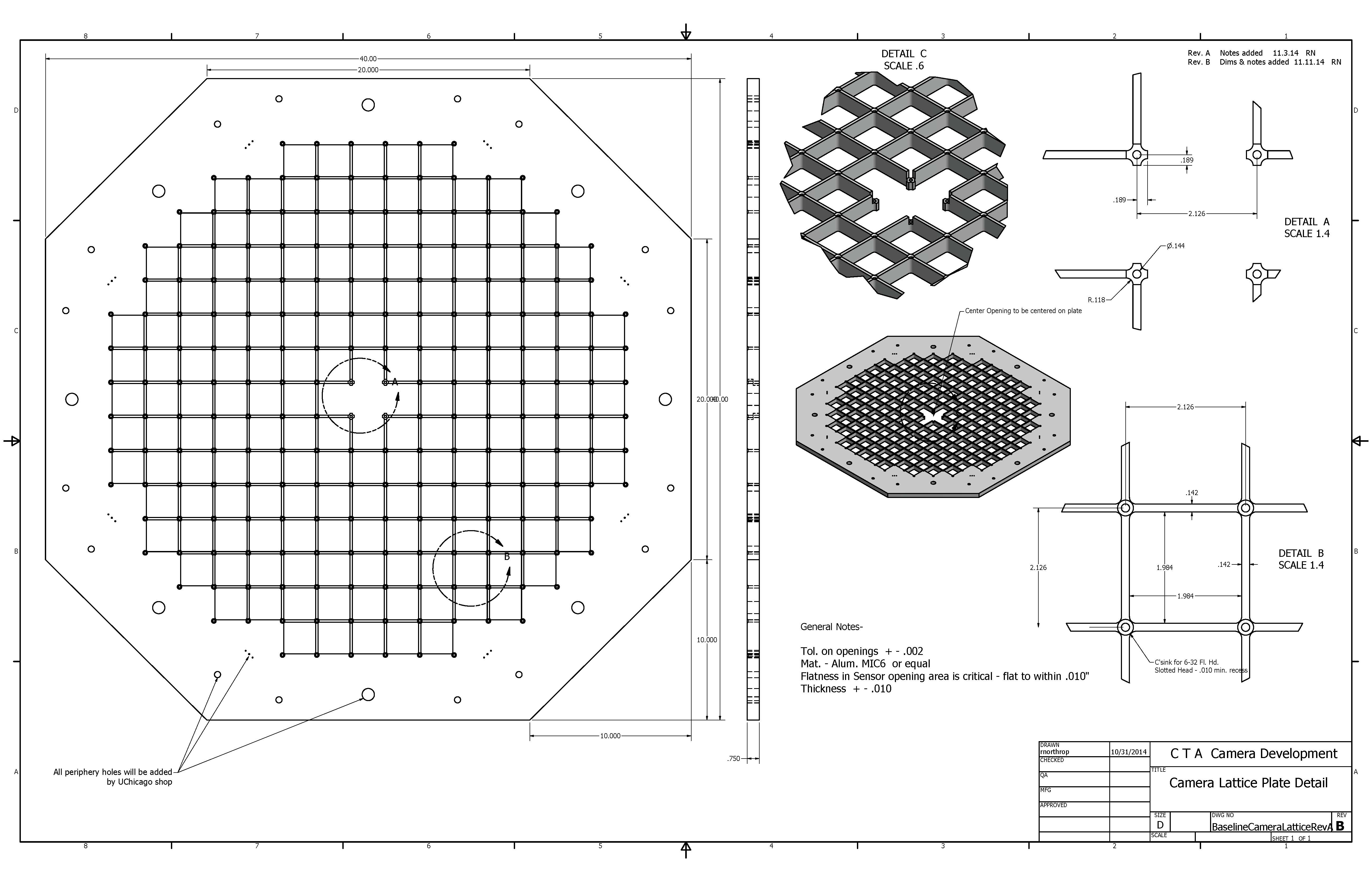 95 |
 96 |
 97 |
 98 |
 99 Bulkhead with center 4 rods & cages for test fit |
 100 Camera housings being assembled- bulkhead, motherboard shroud,& heat exchanger |
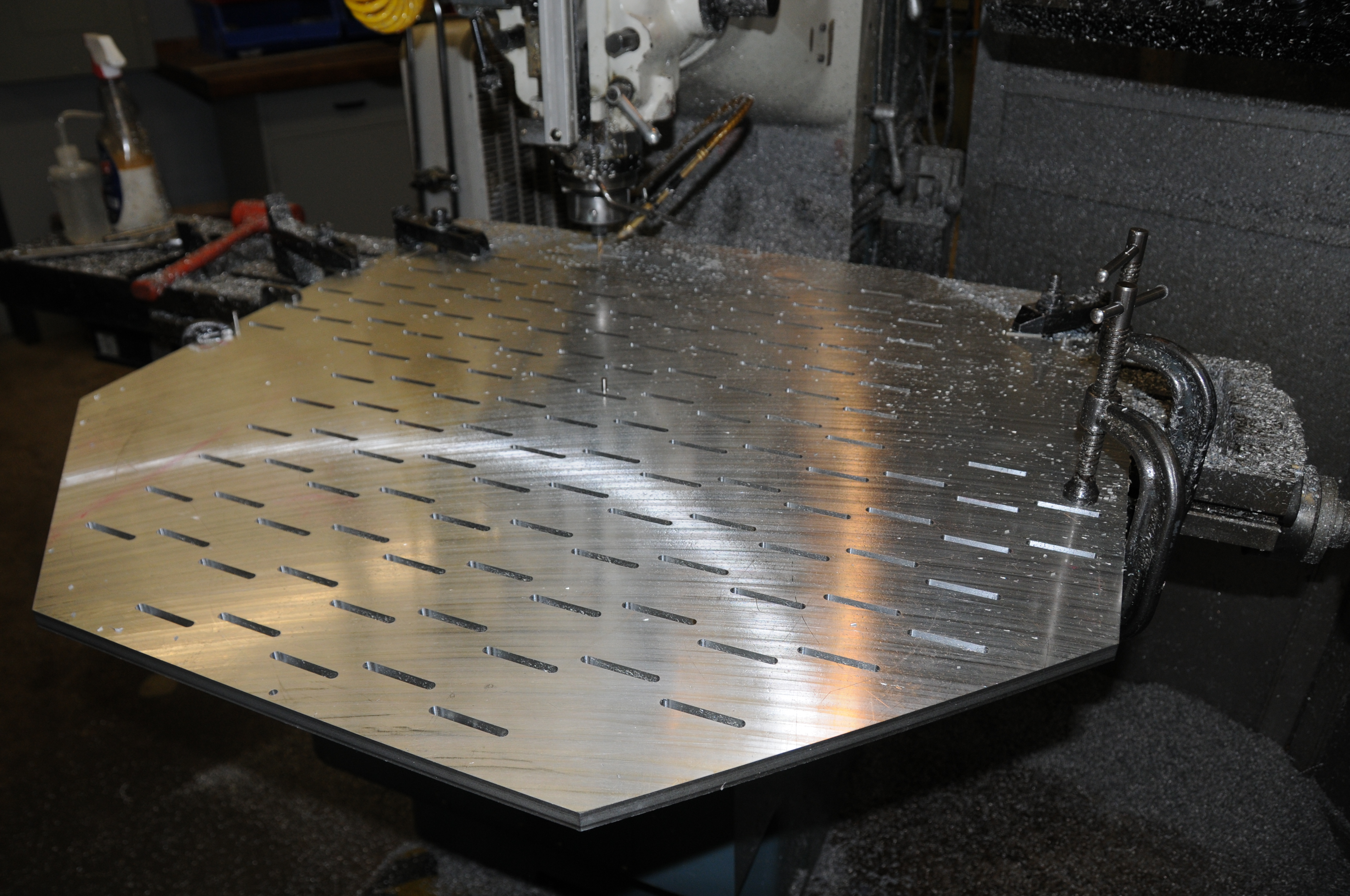
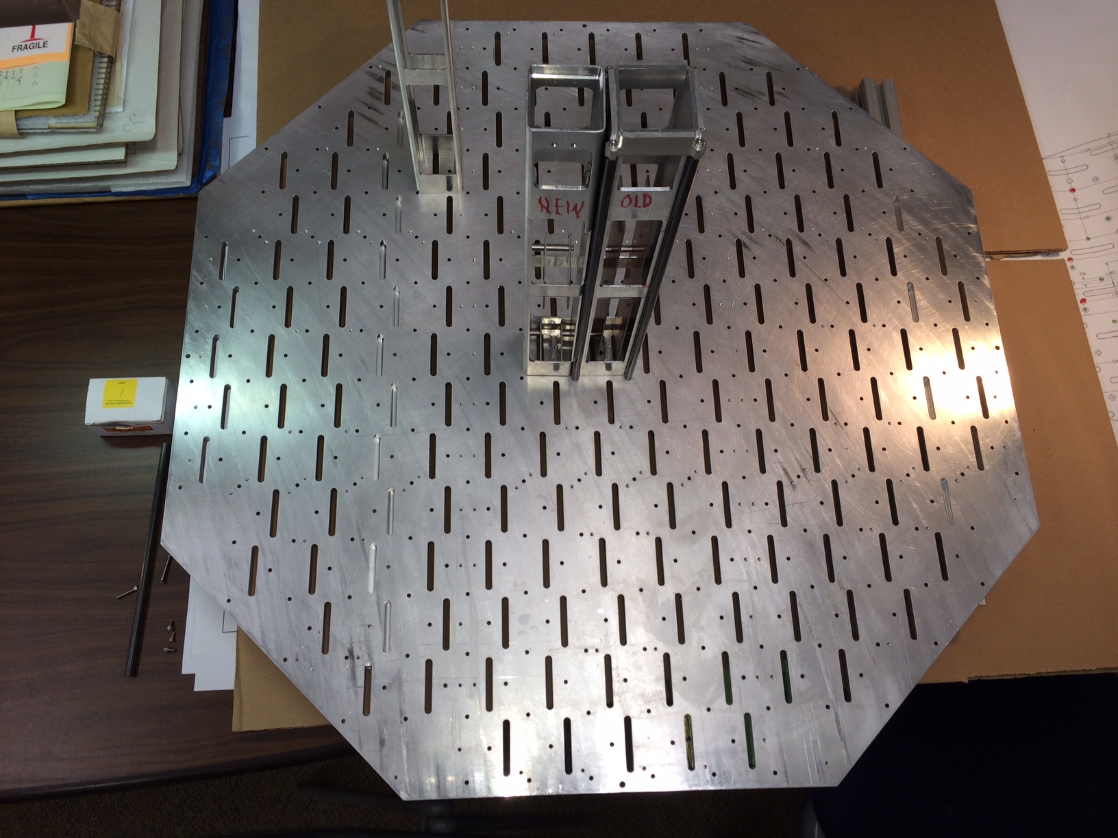
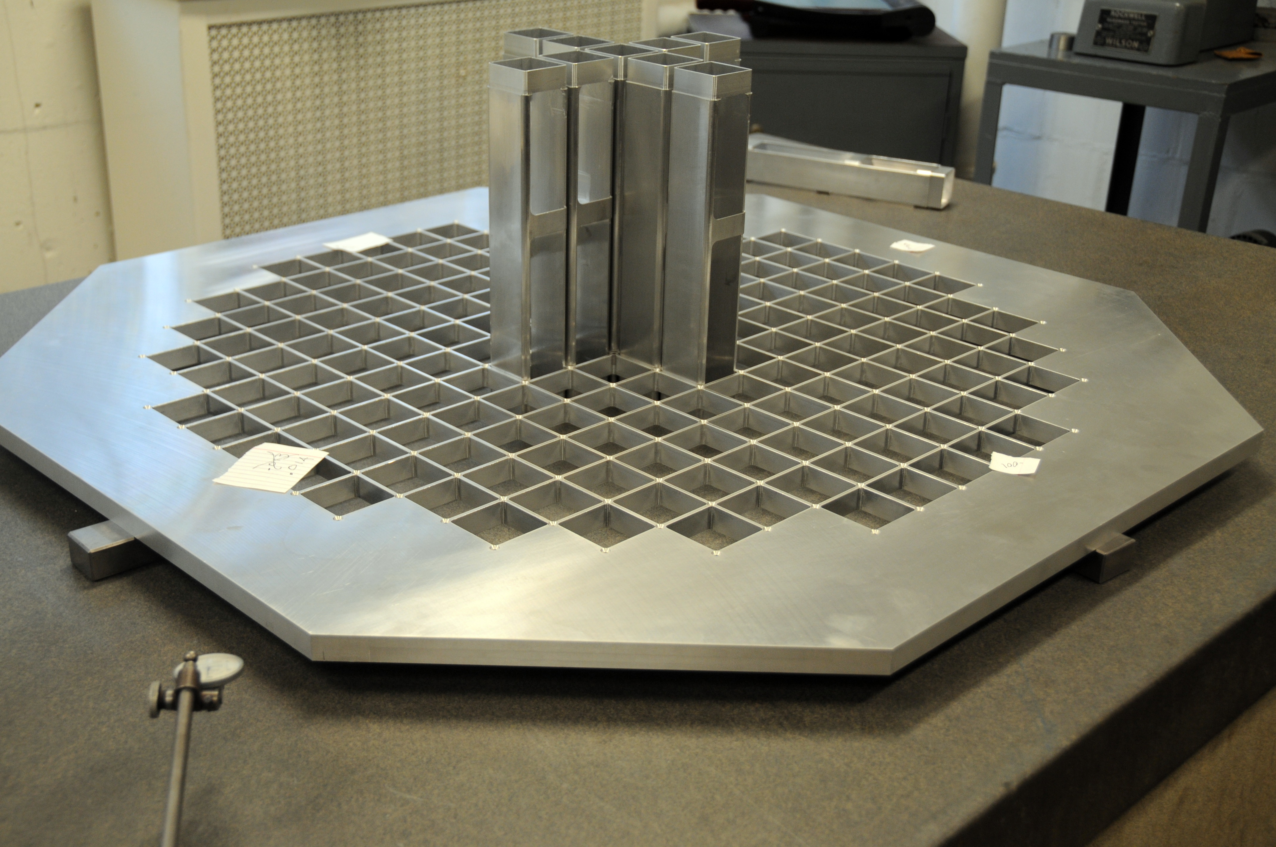 101 Camera Lattice plate delivered and qc’d flat to within .008” |
 102 |
 103 |
 104 |
 105 |
 106 |
 107 |
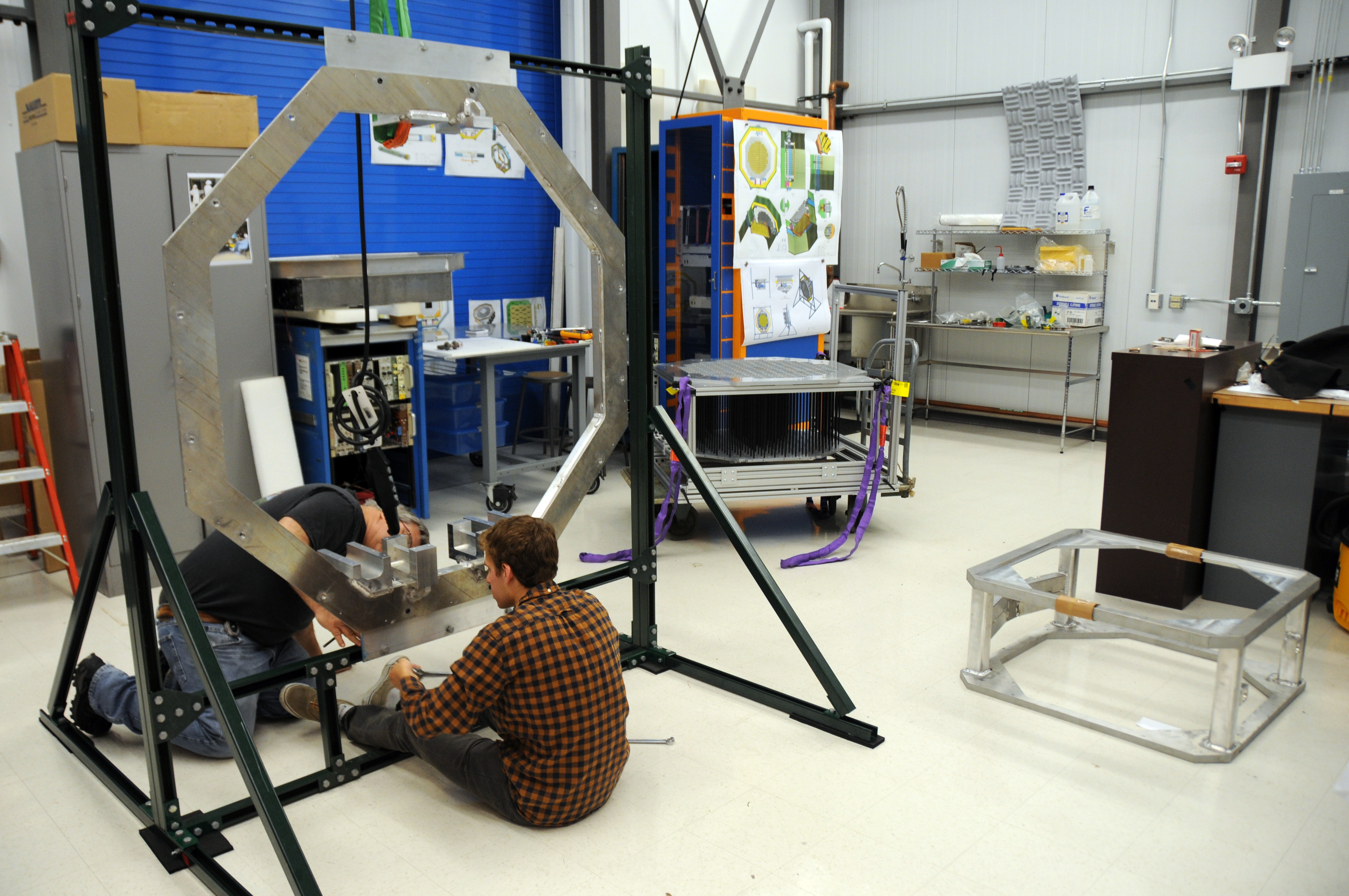
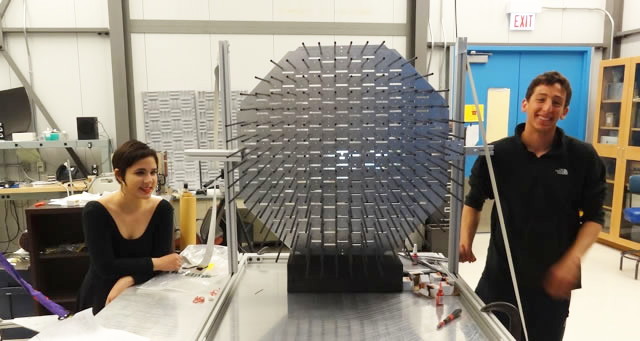 108 CTA engineering students – Samantha and Andrew assembling the camera crate |
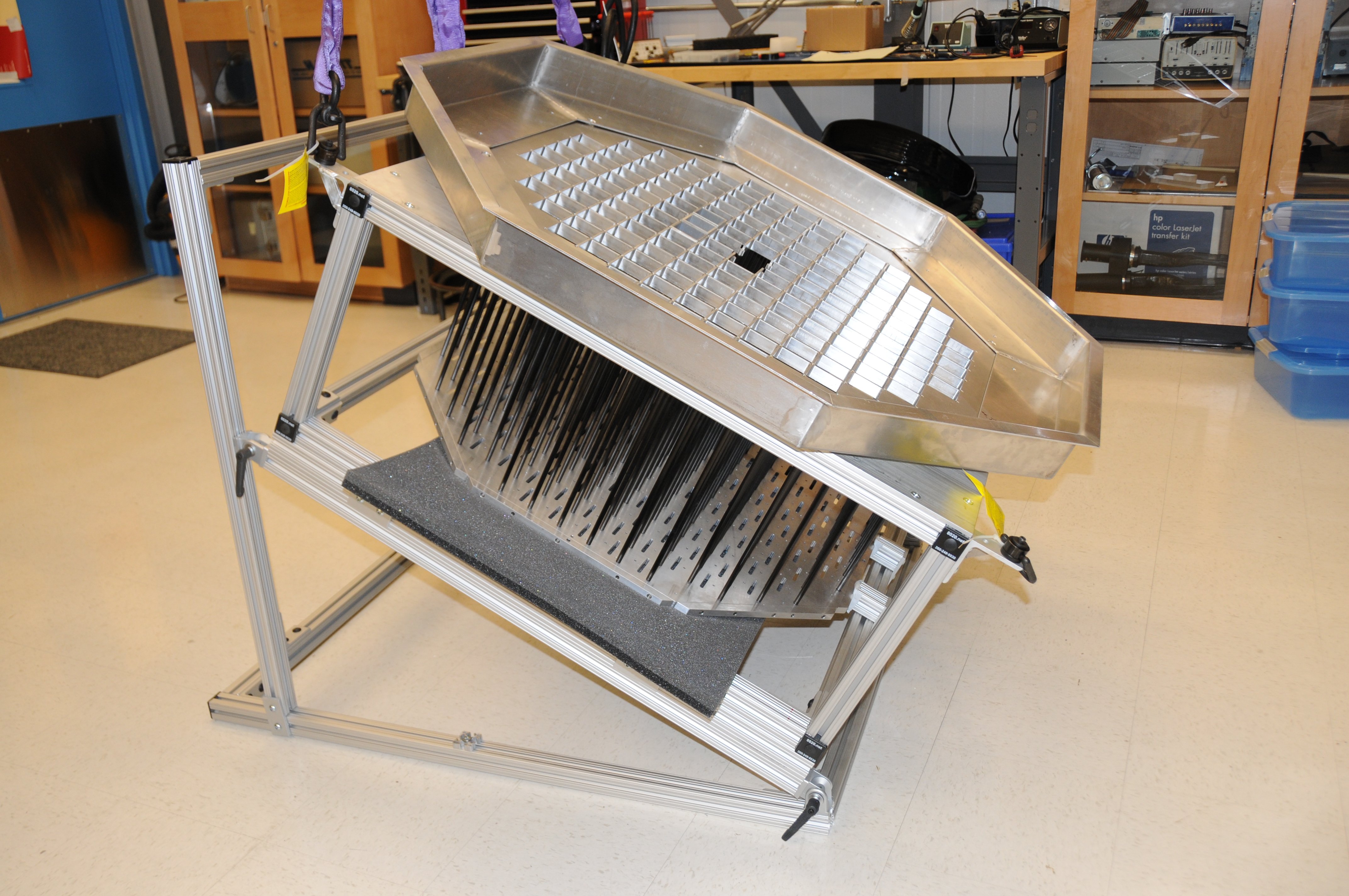 109 Camera Crate in transport frame awaiting trip to FermiLab to be CMM measured and mapped |
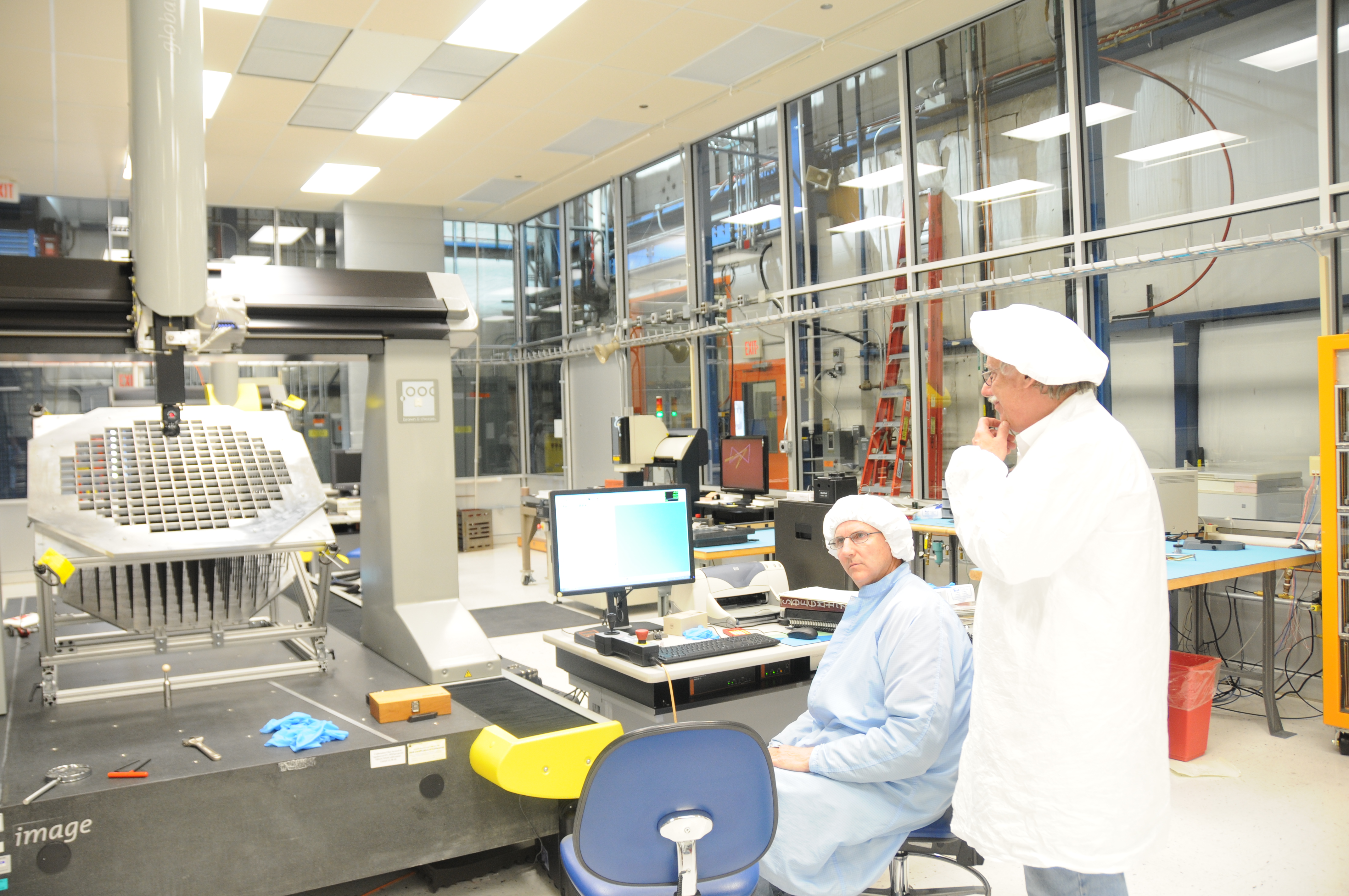 110 Camera crate on CMM watched by operator and Rich Northrop |
 111 Camera hardware being assembled by engineering intern Elliot Weiss and Bob Metz |
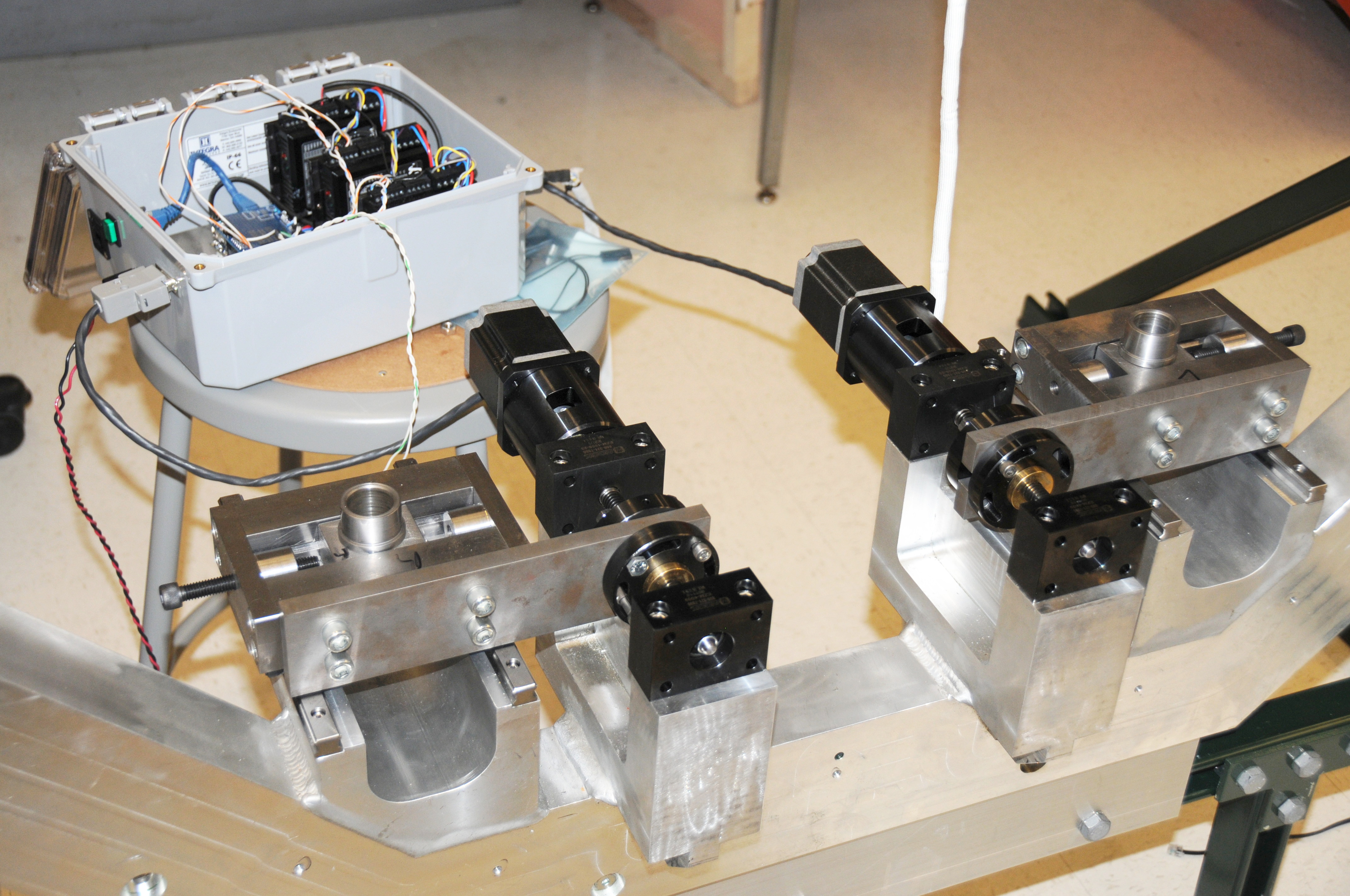
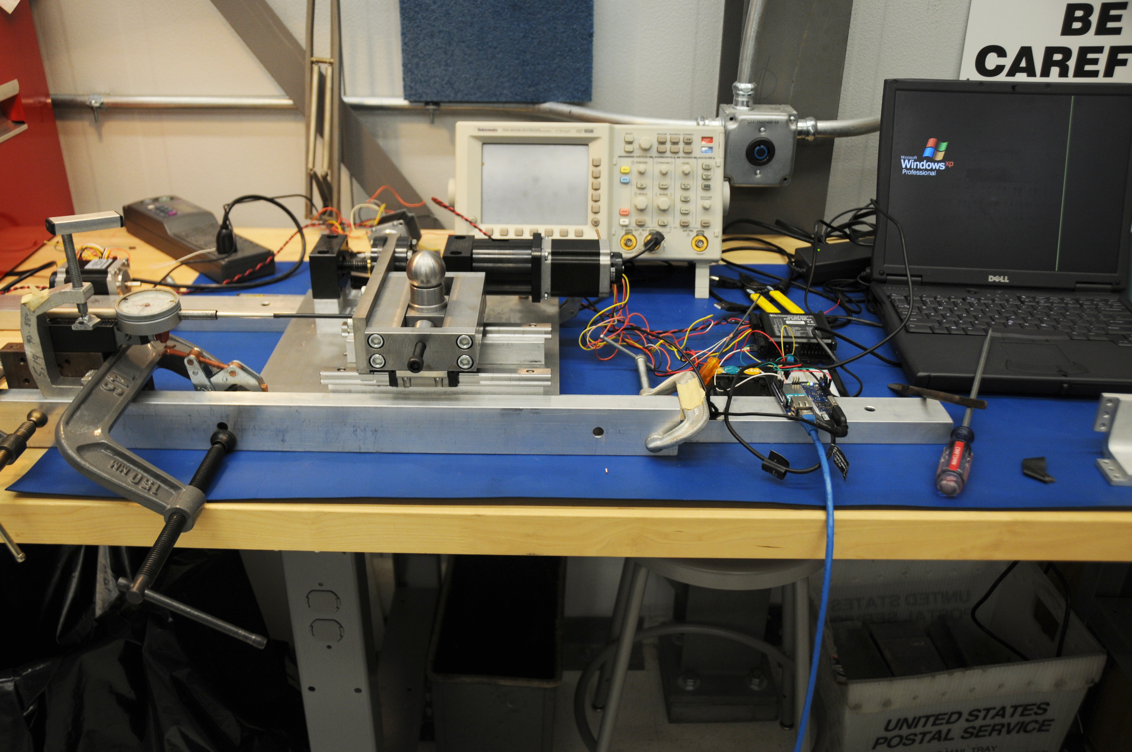 112 Test setup of the camera positioner & controls |
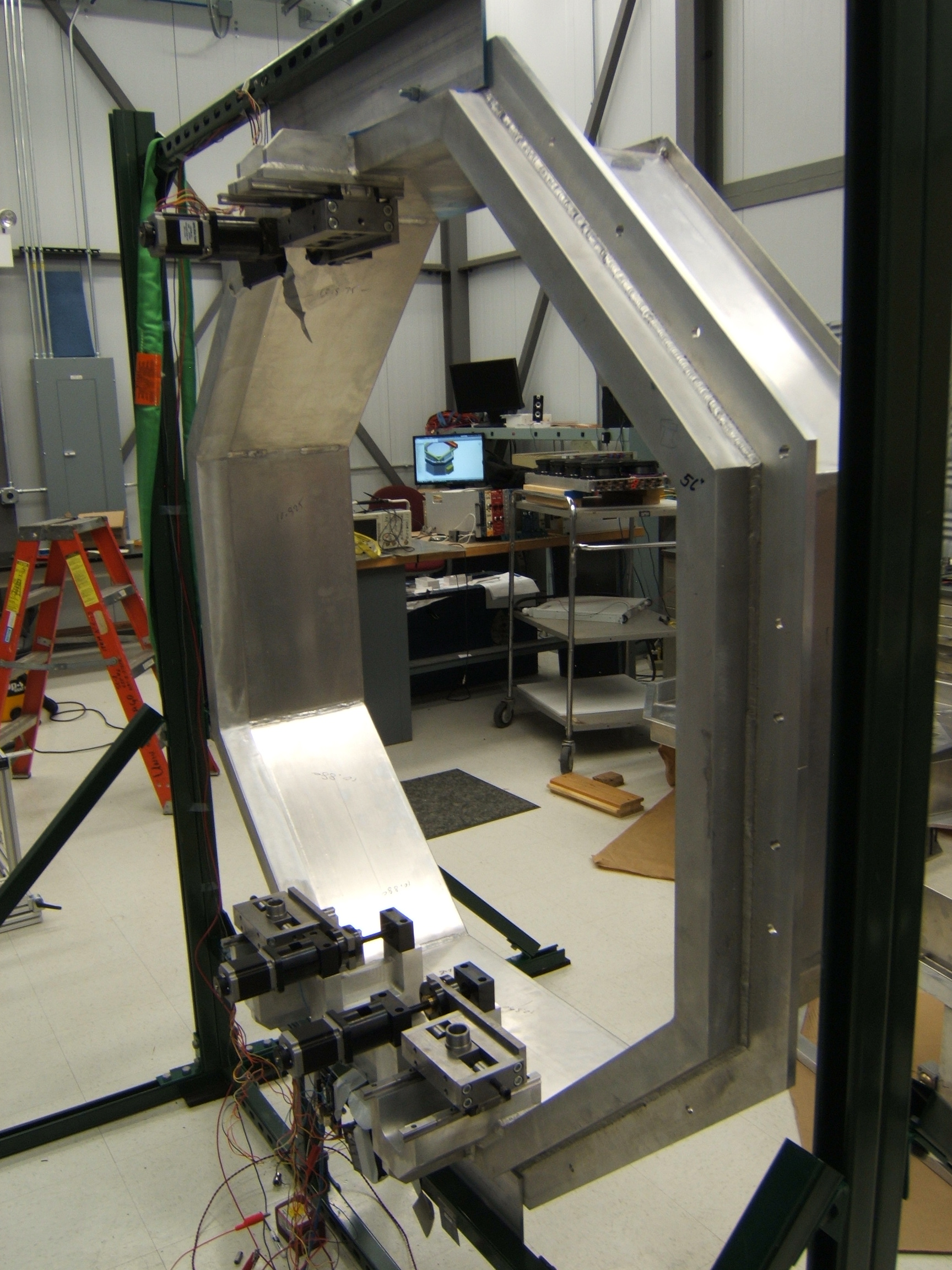 113 Camera mount ring with positioner assemblies and Front shroud mounted |
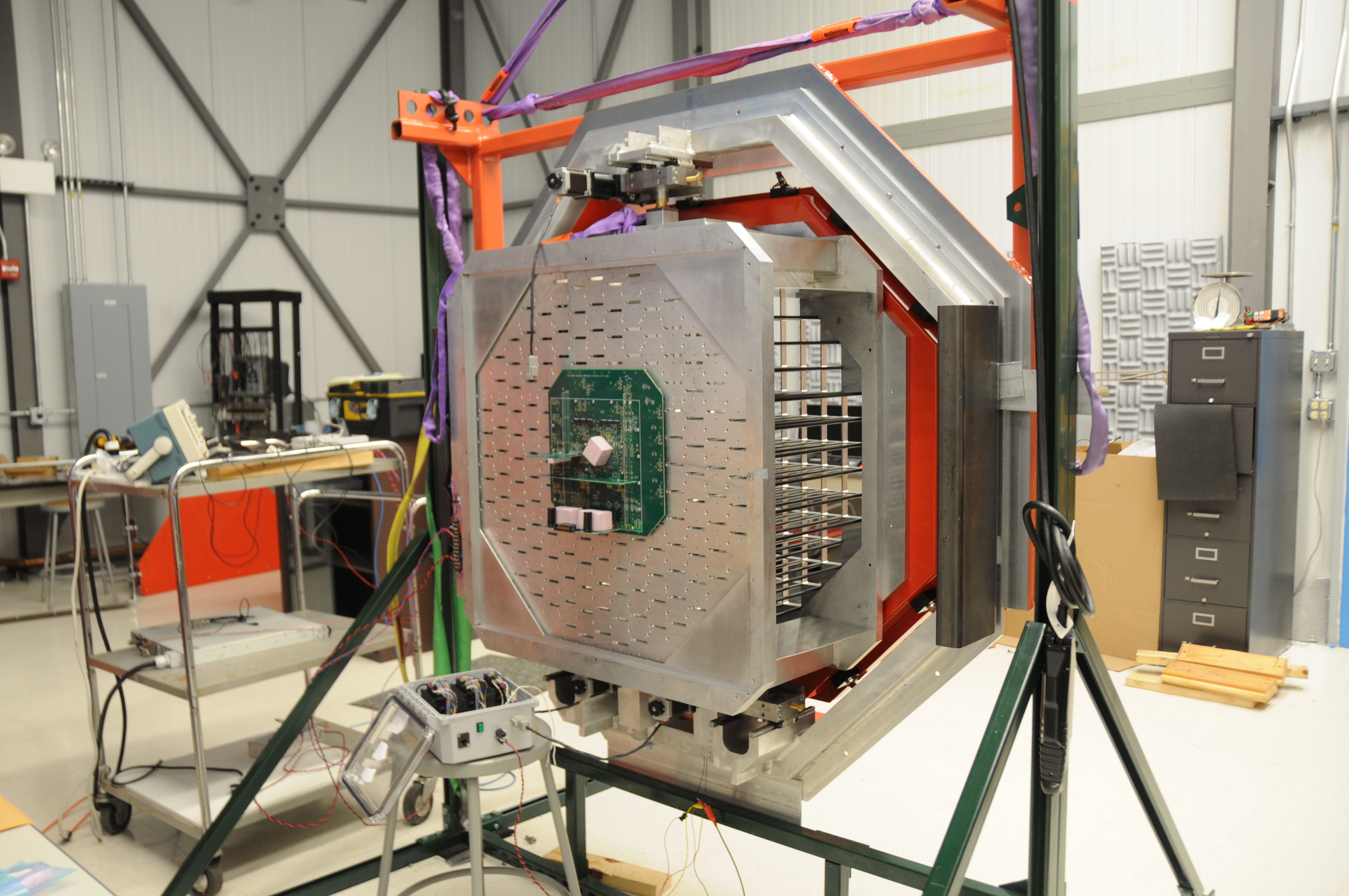
 114 Camera inner structure with rear electronics shroud mounted |
 115 Rear camera shroud being setup on welding table |
 116 The water-proof rear camera shroud and cover being constructed by Bob Metz. |
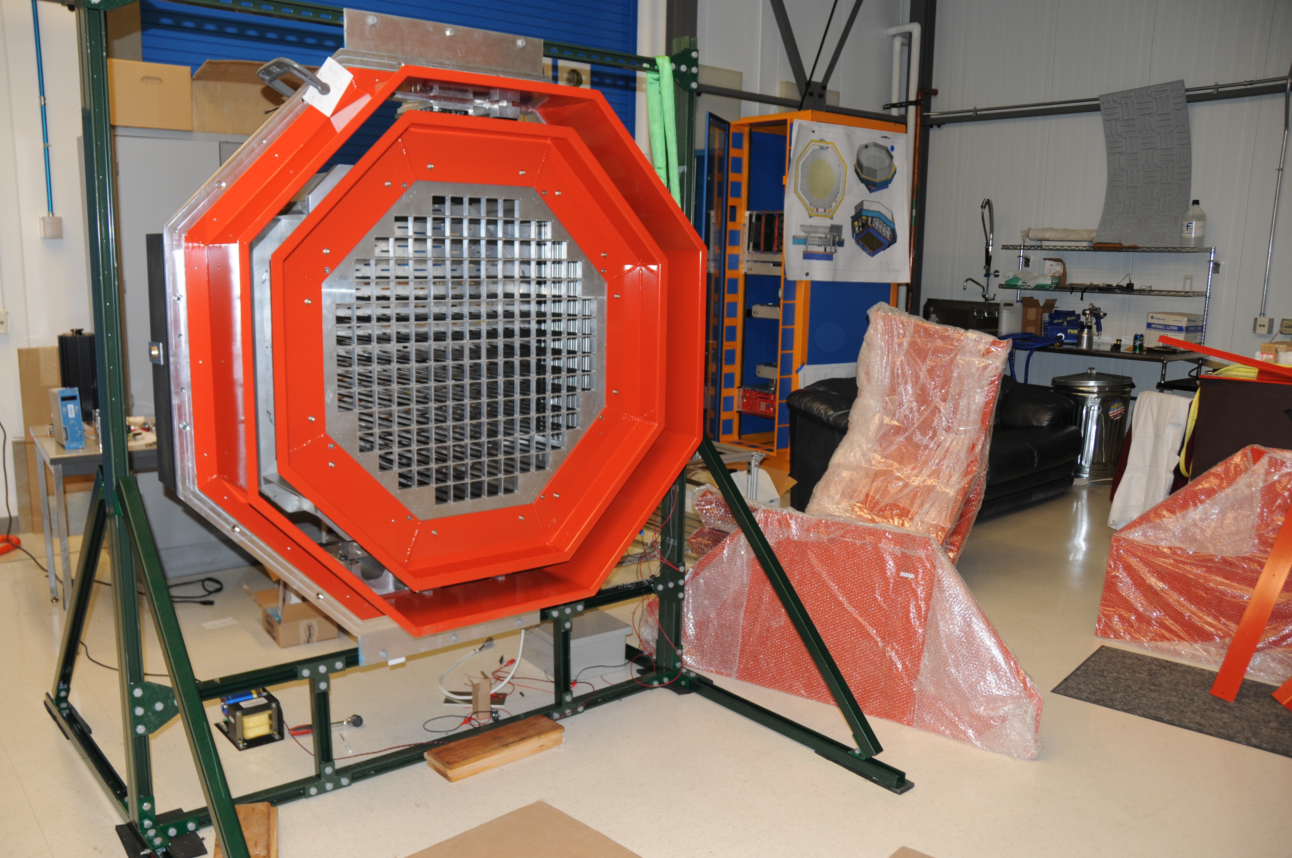 117 camera front view |
 118 rear shroud being fitted to camera |
 119 camera positioner base drives being tested with controller input |
 120 camera front with first 4 sensors installed, lift yoke mounted and window frame attached |
 121 rear view of camera showing central Motherboard mockup |
 122 front camera view during final assembly and testing of positioner and fans |
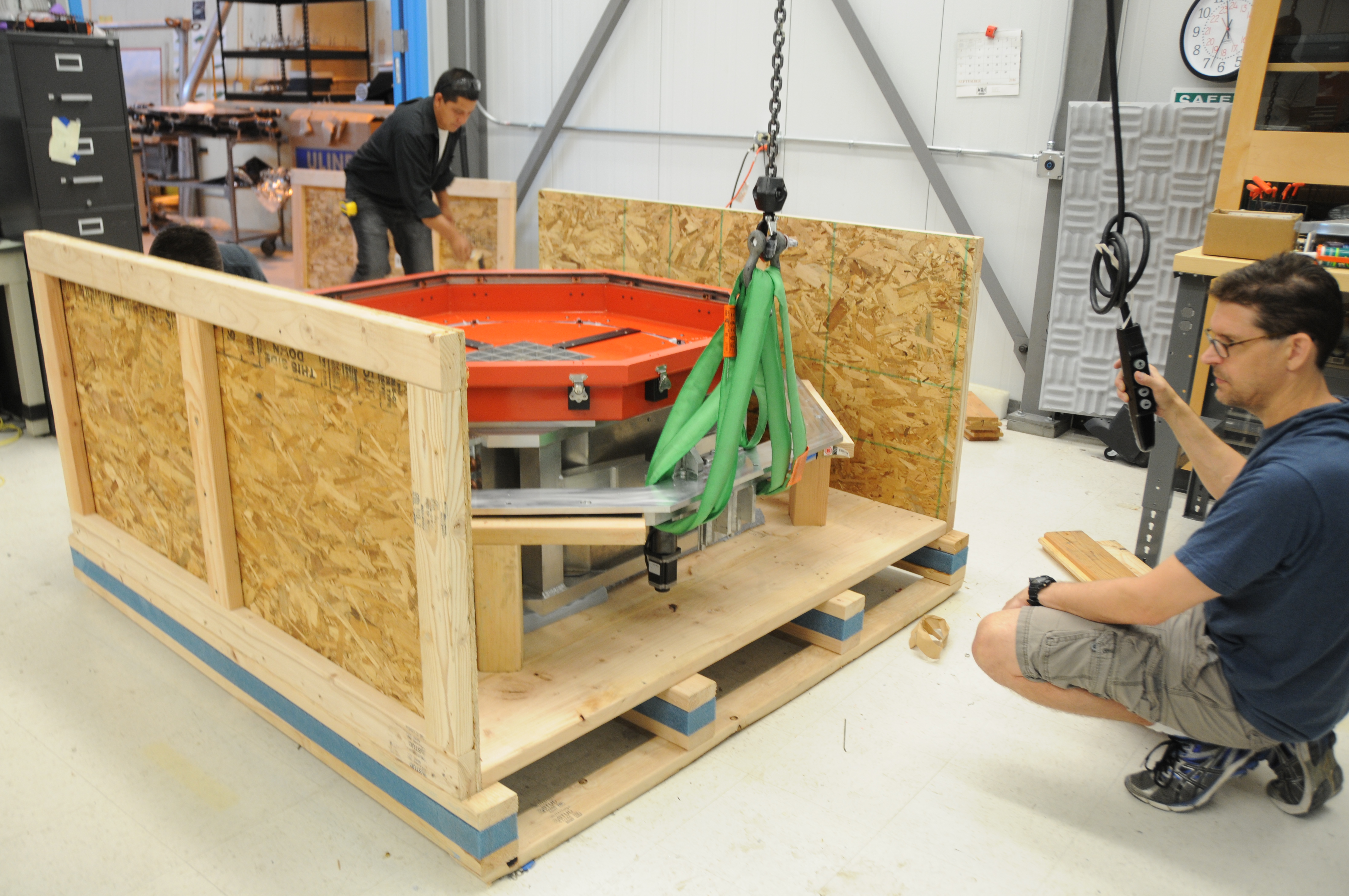 123 Scott Wakely lowers the camera into its shipping crate. |
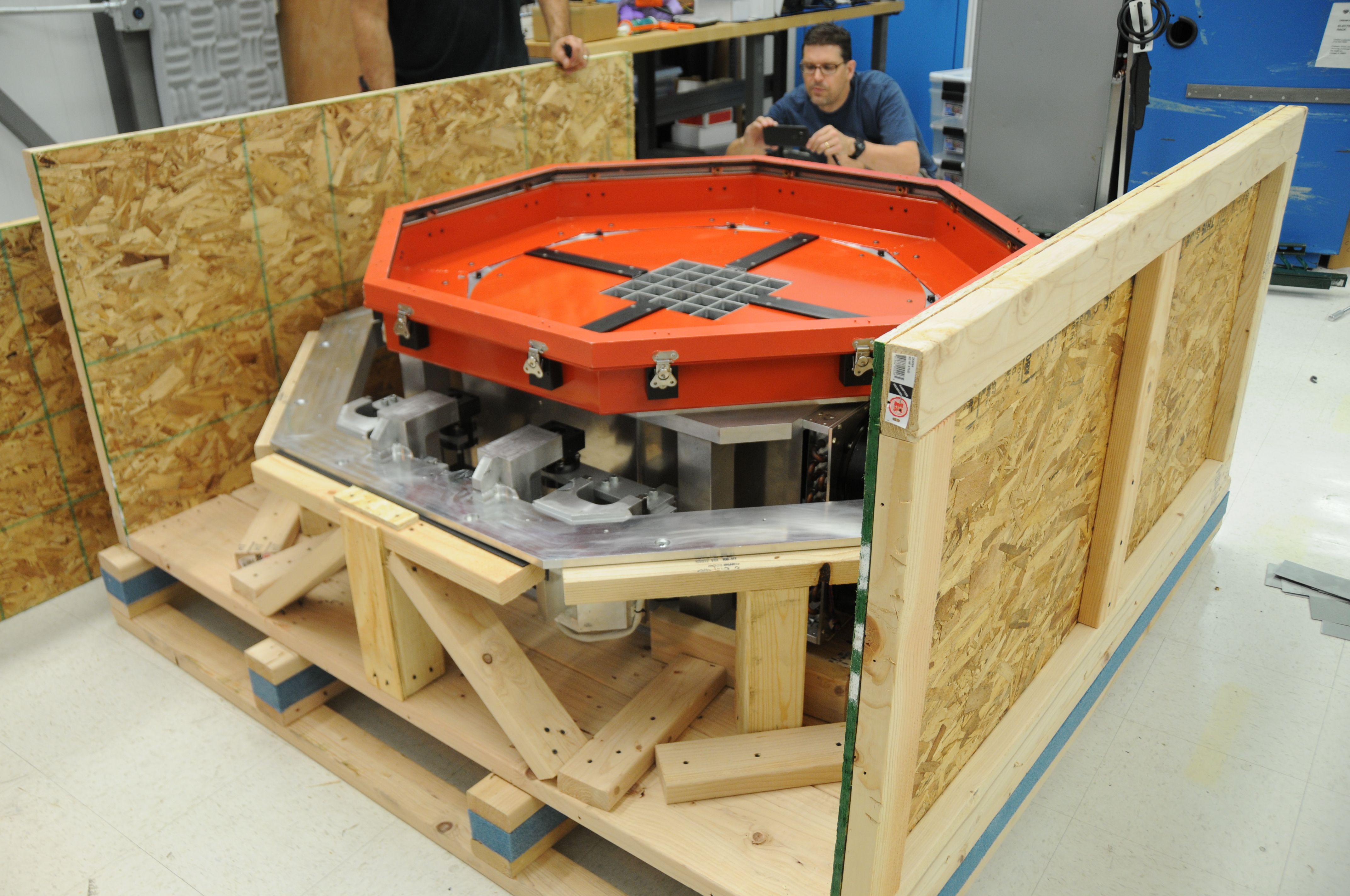 124 camera is ready to be boxed-in and sent to UW for electronics & full sensor installation. |